How To Implement Istio Ambient Mesh in GKE or AKS
Ambient mode is the future of Istio service mesh. This article presents a step-by-step tutorial on how to implement it in GKE or AKS.
Join the DZone community and get the full member experience.
Join For FreeWhy Do You Need Istio Ambient Mesh?
It is given that Istio is a bit resource intensive due to sidecar proxy. Although there are a lot of compelling security features that can be used, the whole Istio (the sidecar) has to be deployed from day one. Recently, the Istio community has reimagined a new data plane — ambient mode — which will be far less resource-intensive. Istio ambient mesh is a modified and sidecar-less data plane developed for enterprises that want to deploy mTLS and other security features first and deploy an advanced network later.
Ambient mesh has two layers:
- L4 secure overlay layer or Ztunnel for implementing mTLS for communication between (services) nodes. Note that Ztunnel is a rust-based proxy.
- L7 processing layer or waypoint proxy for accessing advanced L7 processing for security and networking, thus unlocking the full range of Istio capabilities.

In this blog, we will explain how to implement Isito ambient mesh (with L4 and L7 authorization policies) in Google Kubernetes Engine and/or Azure AKS.
Prerequisite
Please ensure you have the following software or infrastructure in your machine (I’ve used the following):
- Kubernetes 1.23 or later. The version used for implementation: 1.25.6
- Istio 1.18.0-alpha.0
Note: The current version of Istio Ambient mesh (1.18.0v) is in alpha, and a few features might not work, and it may not 100% be stable for production. At this time of the blog, the current version of Ambient mesh is not working with Calico CNI, so accordingly, make your change in Google Kubernetes and Azure Kubernetes (refer to the images below).
![make your change in Google Kubernetes and Azure Kubernetes]()
![make your change in Google Kubernetes and Azure Kubernetes]()
Steps To Implement Istio Ambient Mesh


We will achieve the implementation of Istio ambient mesh with five major steps:
- Installation of Istio ambient mesh
- Creating and configuring services in the Kubernetes cluster
- Implement Istio ambient mode and verify Ztunnel and HBONE
- Enabling L4 authorization for services using ambient mesh
- Enabling L7 authorization for services using ambient mesh
Steps for Installing Istio Ambient Mesh
Step #1: Download and Extract Istio Ambient Mesh From the Git Repo
You can go to the Git repo and download and extract the Istio ambient mesh setup in your local system. (I've used the Windows version). Add <extracted path of Istio installation package>/bin path to the environment path variable.
Step #2: Install Istio Ambient Mesh
Use the following command to install Istio ambient mesh to your cluster.
istioctl install -set profile=ambientIstio will install the following components: Istio core, Istiod, Istio CNI, Ingress gateways, Ztunnel.
Step #3: Check if Ztunnel and Istio CNI Are Installed at the Node Level
After installation, there will be a new namespace created named istio-system. You can check the pods by running the below command.
kubectl get pods -n istio-system -o wideSince I have created two nodes, there are two Ztunnel pods (daemonset) running here.

Similarly, you can use the following command to verify if Istio CNI is installed at the node level.
kubectl get pods -n kube-system
Note: istio-cni is deployed in istio-system namespace in the case of AKS.
Steps To Create and Configure Services in Kubernetes Cluster
Step #1: Create Namespace, Named Ambient for Deployments
kubectl create namespace ambientStep #2: Create Two Services in Separate Nodes
I have used the following YAML for creating deployment.yaml, service.yaml and service-account.yaml. You can refer to the files in the Github repo.
Code for demo-deployment-1.yaml:
apiVersion: apps/v1
kind: Deployment
metadata:
  name: echoserver-depl-1
  namespace: ambient
  labels:
    app: echoserver-depl-1
spec:
  replicas: 2
  selector:
    matchLabels:
      app: echoserver-app-1
  template:
    metadata:
      labels:
        app: echoserver-app-1
    spec:
      serviceAccountName: echo-service-account-1
      containers:
      - name: echoserver-app-1
        image: imeshai/echoserver
        ports:
        - containerPort: 80
Code for demo-service-1.yaml:
apiVersion: v1
kind: Service
metadata:
  name: echoserver-service-1
  namespace: ambient
spec:
  selector:
    app: echoserver-app-1
  ports:
  - port: 80
    targetPort: 80
Code for demo-service-account-1.yaml:
apiVersion: v1
kind: ServiceAccount
metadata:
  name: echo-service-account-1
  namespace: ambient
  labels:
    account: echo-one
Similarly, you can create deployments, services, and service-account files for creating the 2nd service.
Deploy two services in the Kubernetes cluster by using the command:
kubectl apply -f demo-service-account-1.yaml
kubectl apply -f demo-deployment-1.yaml
kubectl apply -f demo-service-1.yaml
You can verify if your pods and svc are running by executing the following commands:
kubectl get pods -n <<namespace>>
kubectl get svc -n <<namespace>>Note: Since I have selected two replicas for each service, Kubernetes automatically created the pods in each node to balance the loads. However, you can explicitly mention in the deployment YAML to create pods in two different nodes as well.

Step #3: Create Istio Gateway and Virtual Services To Allow External Traffic to the Newly Created Services
Once the two services are created, we can create an ingress gateway to allow internet traffic to the newly created services. (The names of my services are echoserver-service-1 and echoserver-service-2 respectively).
I have created a demo-gateway.yaml file (code below) to link to the Istio ingress gateway.
apiVersion: networking.istio.io/v1alpha3
kind: Gateway
metadata:
  name: echoserver-gateway
  namespace: ambient
spec:
  selector:
    istio: ingressgateway
  servers:
  - port:
      number: 80
      name: http
      protocol: HTTP
    hosts:
    - "*"
Code for Istio VirtualService YAML file to route the traffic to service1 and service2 if the URL would match /echo1 and /echo2 respectively.
apiVersion: networking.istio.io/v1alpha3
kind: VirtualService
metadata:
  name: echoserver-virtual-service
  namespace: ambient
spec:
  hosts:
  - "*"
  gateways:
  - echoserver-gateway
  http:
  - match:
    - uri:
        exact: /echo1
    route:
    - destination:
        host: echoserver-service-1
        port:
          number: 80
  - match:
    - uri:
        exact: /echo2
    route:
    - destination:
        host: echoserver-service-2
        port:
          number: 80
Apply the YAML files in the Kubernetes cluster to create an Istio ingress gateway and virtual service objects.
You can check the status of the Istio Ingress gateway resource in the Istio-system namespace by running the command.
kubectl get service -n istio-system
Step #4: Access the Services From the Browser
You can use the external IP address of the Istio gateway to access the services.

By default, the communication will not go through the Ztunnel of the Istio ambient mesh. So we have to make it active by applying certain commands.
Steps To Verify Communication Through Ztunnel (mTLS) In Ambient Mesh
Step #0 (Optional): Log the Ztunnel and Istio CNI
This is an optional step you can use to observe the logs of Ztunnel and Istio CNI while transitioning service communication to Istio ambient mode. You can apply these commands:
kubectl logs -f <<istio-cni-pod-name>> -n kube-system
kubectl logs -f <<ztunnel-pod-name>> -n istio-system
Step #1: Apply Ambient Mesh to the Namespace
You need to apply Istio Ambient mesh to the namespace by using the following command:
kubectl label namespace ambient istio.io/dataplane-mode=ambientBoth services would be a part of the Istio ambient service mesh now. You can verify by accessing them again from the browser.
Step #2: Verify the Communication Through Ztunnel of External Traffic
If you login to the browser and try to access the services (echoserver-service-1 and echoserver-service-2 for me), you will see the communication is already happening through the Ztunnel.

Step #3: Verify the HBONE of Service-To-Service Communication
You can also verify if your service-to-service communication is secured by letting one pod to communicate with another (and then check the logs of ztunnel pods).
Log into one of the pods of service (say echoserver-service-1) and use bash to send requests to another service (say echoserver-service-2).
You can use the following command to go to bash of one pod:
kubectl exec -it <<pod name of service-1>> -n <<namespace>> –- bashUse curl to send the request to another service.
curl <<service-2>>You will see in the logs of one of Ztunnel pods that the communication is already happening over the HBONE (a secure overlay tunnel for communication between two pods in different nodes).

Step #4: Verification of mTLS-Based Communication in Service-To-Service Communication
Connect to ssh of one of the nodes to dump TCP packets and analyze the traffic request; we will understand if the communication between two nodes is going through the secure channel or not.
Execute the following command in the node-ssh: (15008 port is used for HBONE communication in Istio ambient mesh). We will write the logs into node1.pcap
sudo tcpdump -nAi ens4 port 9080 or port 15008 -w node1.pcapYou can curl a service from one pod and check the node logs (download node1.pcap file), and when you open the file in the network analyzer, it would show something like the below:

You will observe that all the application data exchanged between the two nodes are secured and using mTLS encryption.
Steps To Create L4 Authorization Policies in Istio Ambient Mesh
Step #1: Create an Authorization Policy Yaml in Istio
Create a demo-authorization-L4.yaml file to write policies that would allow public traffic to the service-1 containers only and not from any other services. We have mentioned in the rules to allow traffic from the Istio ingress controller.
apiVersion: security.istio.io/v1beta1
kind: AuthorizationPolicy
metadata:
name: echoserver-policy
namespace: ambient
spec:
selector:
matchLabels:
app: echoserver-app-1
action: ALLOW
rules:
- from:
- source:
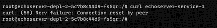
principals: ["cluster.local/ns/istio-system/sa/istio-ingressgateway-service-account"]Use the command to apply the YAML file.
kubectl apply -f demo-authorization-L4.yamlNote: Once you try to reach our service-1 (echoserver-service-1) from the browser, then you can access it without any problem. But if you curl from one of the pod of service-2, it would fail (refer to the screenshot).
Steps To Create L7 Authorization Policies Using Waypoint Proxy
For L7 authorization policies, we have to create a way-point proxy. The waypoint proxy can be configured using K8s gateway API. Note: by default, the gateway API CRDs might not be available in most of the cloud providers, so we need to install them.
Step #1: Download Kubernetes Gateway API CRDs
Use the command to download gateway API CRDs using Kustomize.
kubectl kustomize “github.com/kubernetes-sigs/gateway-api/crd?ref=v0.6.1” > gateway-api.yaml
Step #2: Apply Kubernetes Gateway API
Use the command to apply gateway API CRDs.
kubectl apply -f gateway-api.yaml
Step #3: Create Waypoint Proxy of Kubernetes Gateway API Kind
We can create a waypoint proxy of the gateway API with a YAML file. You can use the demo-waypoint-1.yaml. We have basically created a waypoint proxy for service-1 (echoserver-service-1).
apiVersion: gateway.networking.k8s.io/v1beta1
kind: Gateway
metadata:
  name: echoserver-gtw-1
  namespace: ambient
  annotations:
    istio.io/for-service-account: echo-service-account-1
spec:
  gatewayClassName: istio-waypoint
  listeners:
  - allowedRoutes:
      namespaces:
        from: Same
    name: imesh.ai
    port: 15008
    protocol: ALL
And apply this to the K8s cluster.
kubectl apply -f demo-waypoint-1.yaml
Step #4: Create L7 Authorization Policy To Declare the Waypoint Proxy for Traffic
Create an L7 authorization policy to define rules for when to apply the waypoint proxy (echoserver-gtw-1) for traffic. You can use the following demo-authorization-L7.yaml file to write the policy.
apiVersion: security.istio.io/v1beta1
kind: AuthorizationPolicy
metadata:
  name: echoserver-policy
  namespace: ambient
spec:
  selector:
    matchLabels:
      istio.io/gateway-name: echoserver-gtw-1
  action: ALLOW
  rules:
  - from:
    - source:
        principals: ["cluster.local/ns/istio-system/sa/istio-ingressgateway-service-account"]
    to:
    - operation:
        methods: ["GET"]
Use the command to apply the YAML file.
kubectl apply -f demo-authorization-L7.yaml
Step #5: Verify the L7 Authorization Policy
As we have created a waypoint proxy for service-1 and applied a policy to allow all traffic from the Istio ingress gateway, you will see you can still access service-1 (echoserver-service-1) from the browser.
However, if you want to access service-1 from one of the pods of service-2 (echoserver-service-2), the waypoint proxy will not allow the traffic as per the policy (refer to the screenshot below).

Ambient Mode: The Future of Istio Service Mesh
I feel that ambient mesh will drive Istio adoption to new heights in the coming years. With its ability to simplify application onboarding to Istio and reduce infrastructure costs, ambient data plane mode is poised to become the future of Istio service mesh.
Published at DZone with permission of Ravi Verma. See the original article here.
Opinions expressed by DZone contributors are their own.
Comments