

How To Visualize Temporal.io Workflows
Temporal is a great workflow engine. This project demonstrates how temporal can be enhanced to provide a visual representation of workflows.
I hope everyone knows about Temporal.io — a great workflow engine. If not, please familiarize yourself with it and start using it. You will love it, and it will save you millions of dollars and many months of development time.
In short, Temporal.io allows us to write workflows in a programming language of our choice, Unit test them (!!!), and then run them in a distributed environment.
The platform is very stable, reliable, fast, and secure. Developers love it, but when it comes to ‘selling’ it to management and business people, it gets challenging because there is no visual representation of the workflow runtime state as a diagram. Business people love diagrams, and that allows con artists from low/no-code platforms to sell their snake oil (Appian, Jitterbit, etc.).
Well, we can do better, and this project demonstrates how temporal can be enhanced to provide a visual representation of workflows.
Note: Even though this project is written with Kotlin and runs on a JVM platform, the same approach can be used with any other language and platform supported by Temporal.
Concepts
Worflows provide two query methods:
- One that returns workflow definition in PlantUML format
- Another that returns the name (or names) of current active states
A helper utility can be used to make those queries, enhance PlantUML definition with current state information, and create PlantUML server URL with encoded diagram. POC grade implementation can be found at this GitHub link.
I hope that the Temporal team will adopt this (or similar) approach and provide built-in support for workflow visualization from their UI. For now, we can implement this approach in our custom dashboard for workflows.
The demo project can be found on GitHub here.
Prerequisites
- A computer with OS X or Linux (Windows can be used too if one likes pain )
- Java 21
- Maven (sdk install maven)
- Temporal CLI (brew install temporal)
- Python3 (brew install python3)
- Docker
- Check out this project
cd visual-workflow-apimvn install- Check out the Visualizer project
Now, we are ready to experiment.
Workflow Implementation
Workflow Diagram
We can start by defining the workflow in planUML syntax and visualize it using the excellent IntelliJ plugin for PlantUML.
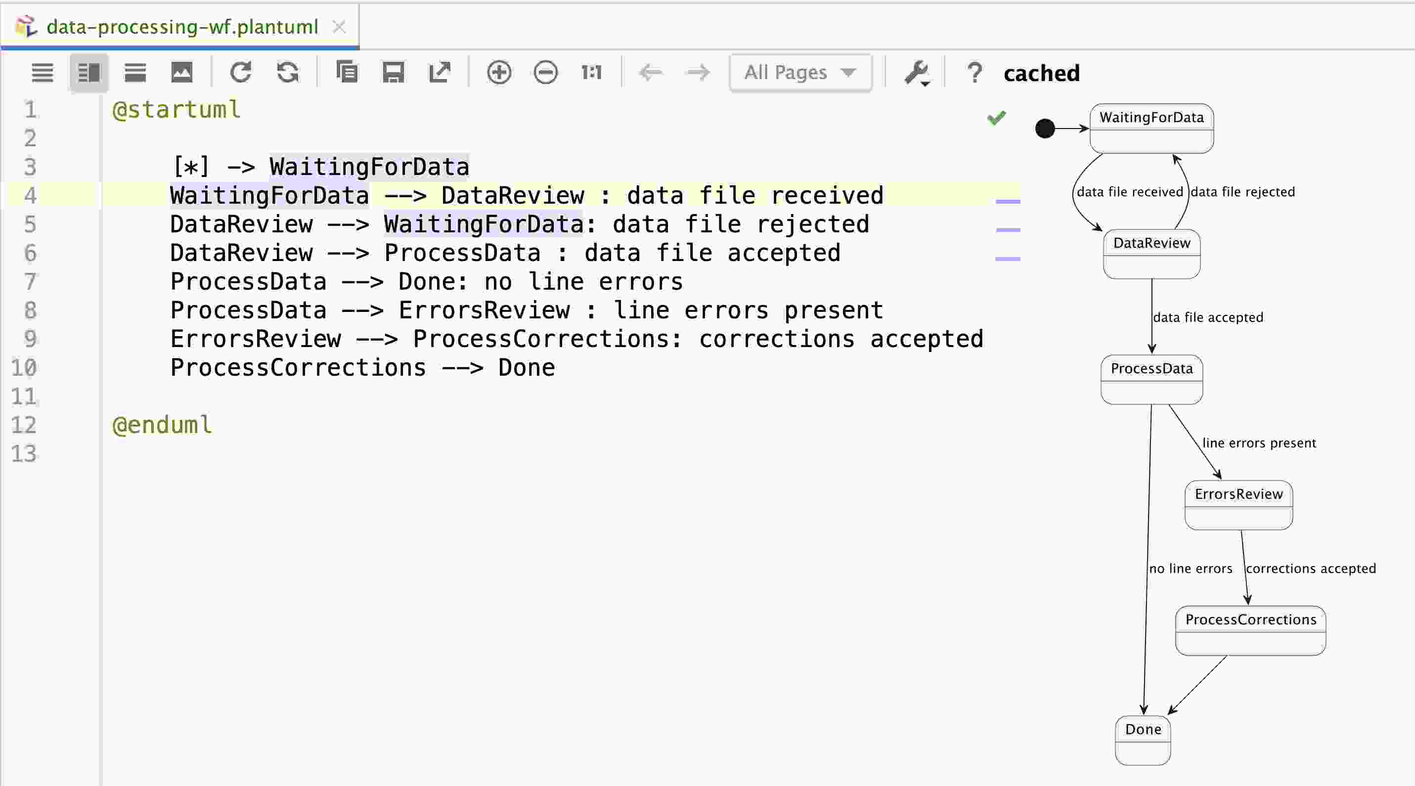
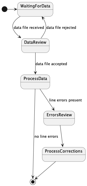
As we can see, the workflow is defined in a very abstract way, and we can have a good visualization of workflow.
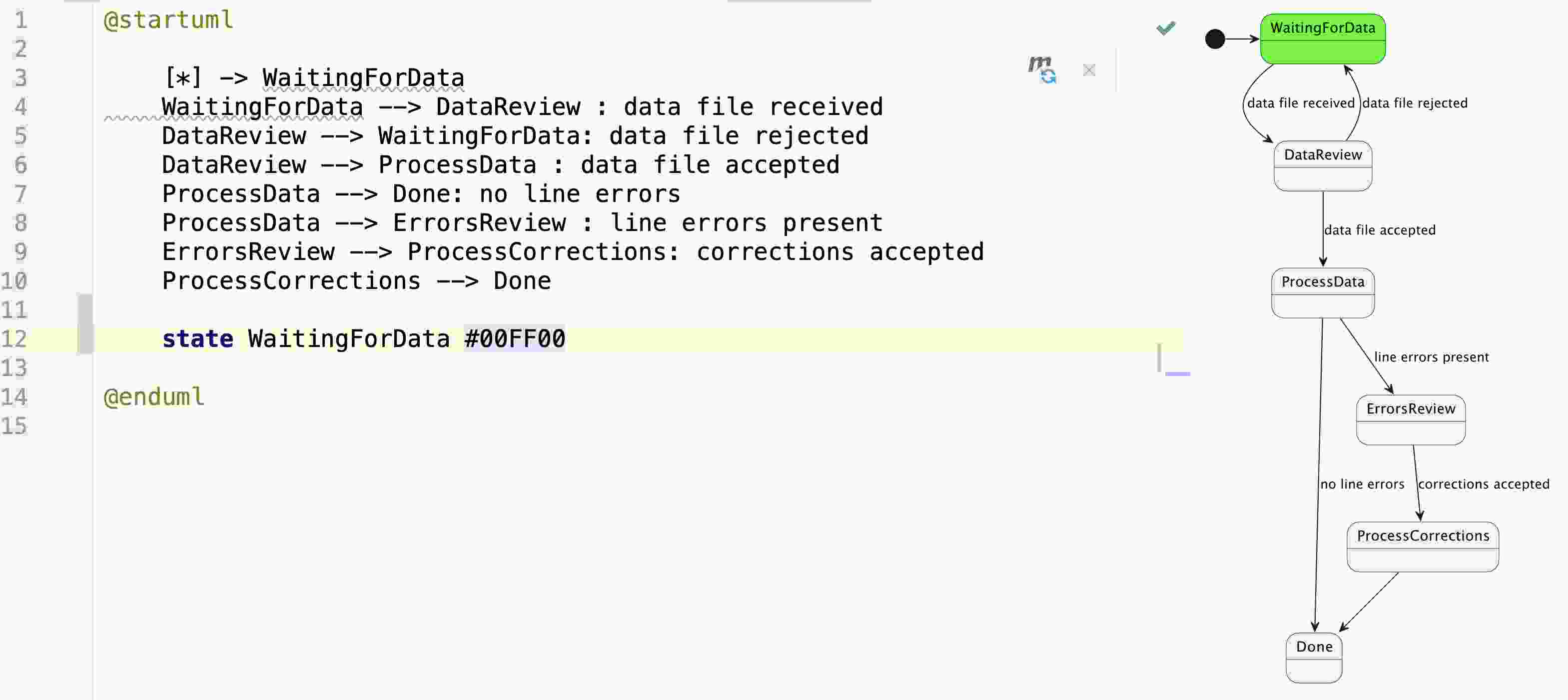
To colorize the diagram, we simply need to add lines like ‘state #’ to the diagram definition. So, our helper script simply needs to prepend the closing tag with those lines. The workflow diagram will look like this:
Workflow Definition
The workflow is a Final State Machine (FSM), and we can define it by using a domain-specific language or a library. In this example, we use kstatemachine library.
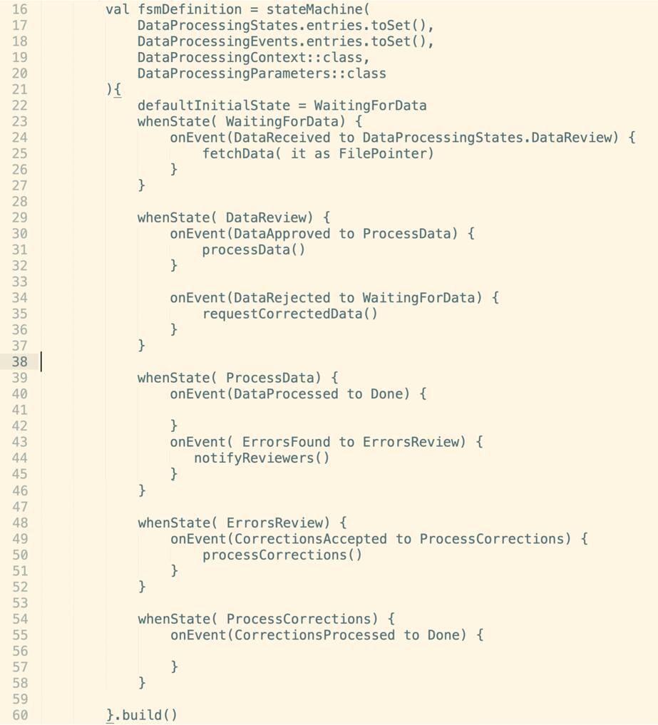
Thanks to the kstatemachine library, our workflow definition is as readable as our abstract definition, but we benefit from the type safety and IDE support — the definition is in Kotlin language, and we can use all the power of Kotlin and IDE to simplify implementation.
Note: A different SDK can be used to implement Temporal workflows or even a mix of SDKs; for example, workflow can be in Python and Activities in JavaScript.
Workflow Execution Demo
Run Temporal Server
In a separate terminal window, run Temporal Server:
cd <project-root>/temporal
docker compose up
In another separate terminal window run our workflow and activities implementations
cd <project-root>
mvn spring-boot:run
Execute Workflows and Visualize State
Open a separate terminal window at the project root
./scripts/start-wf.sh
This will return a workflow ID, for example:
Running execution:
  WorkflowId  a23da575-3ae3-43cf-bd0d-886470f34644
  RunId       796b833d-3348-472d-93fe-0610668cac77
  Type        DataProcessingWF
  Namespace   default
  TaskQueue   data-processing-wf
  Args        ["account42"]
Then, we make the workflow ID available for our helper scripts:
export WFID=a23da575-3ae3-43cf-bd0d-886470f34644
At this point, we can see the workflow state in the Temporal Web UI by opening this local host.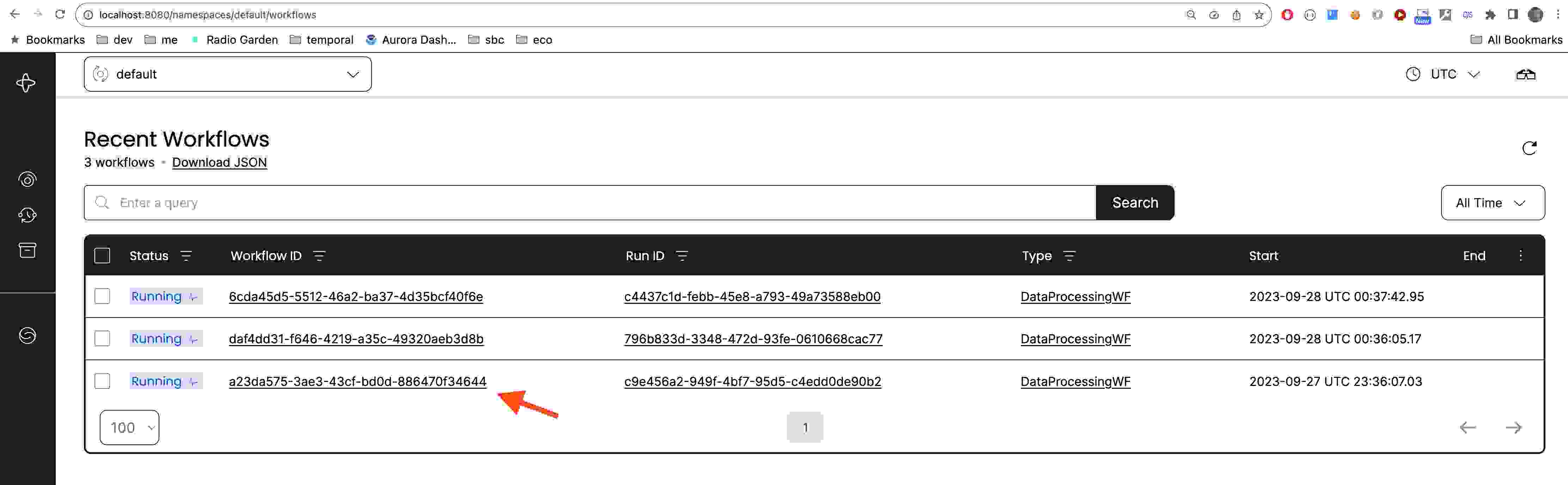
And we can see the workflow state and workflow definition in the console :
./scripts/send-query.sh getWorkflowInfo
Query result:
[{"legend":"Account: account42","activeStates":[{"stateName":"WaitingForData","isError":null,"comment":null}]}]

 ./scripts/send-query.sh getPlantUMLWorkflowDefinition

Query result:
["@startuml\n\n    [*] -> WaitingForData\n    WaitingForData --> DataReview : data file received\n    DataReview --> WaitingForData: data file rejected\n    DataReview --> ProcessData : data file accepted\n    ProcessData --> Done: no line errors\n    ProcessData --> ErrorsReview : line errors present\n    ErrorsReview --> ProcessCorrections: corrections accepted\n    ProcessCorrections --> Done\n\n@enduml\n"]
We can run Visualizer Helper, which will open a browser window with the workflow diagram:
./scripts/visualize-wf.sh
Note the PlantUML URL starts with ~h. That is because simple HEX encoding was used, but it can be more efficient with using PlantUML-recommended compression.
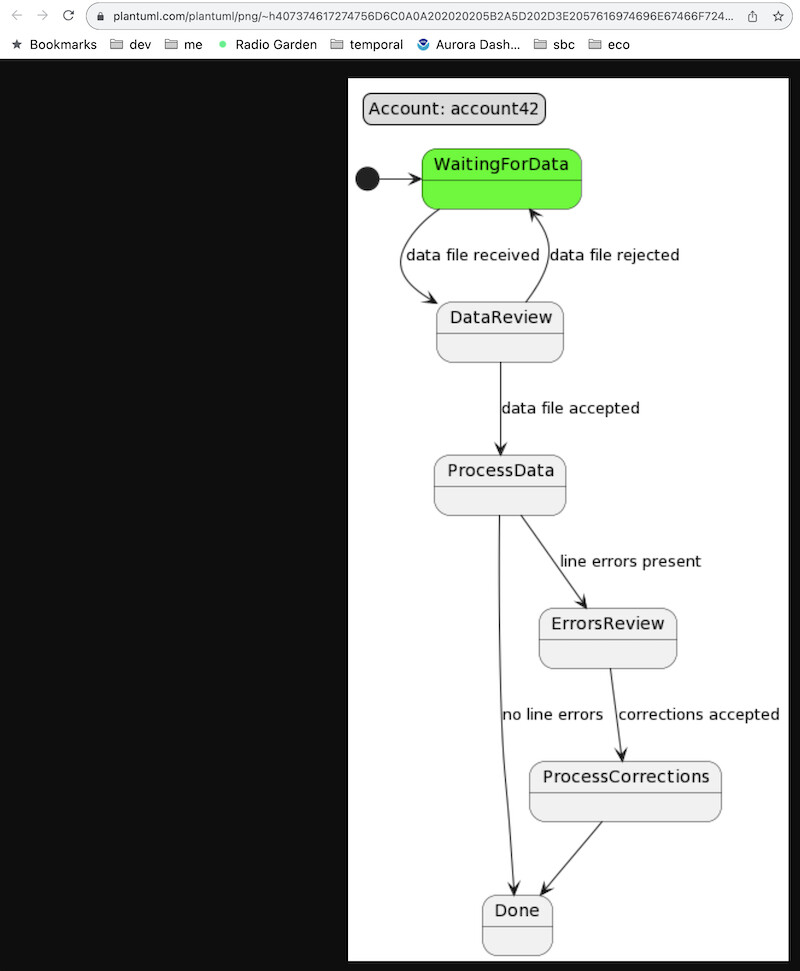
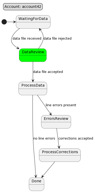
Then we can send a signal to advance workflow and then visualize it again:
./scripts/send-signal.sh dataReceived file321
./scripts/visualize-wf.sh
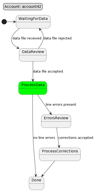
Now we can send another signal to advance workflow:
./scripts/send-signal.sh dataApproved
./scripts/visualize-wf.sh
Conclusion
In real life, we usually create a custom dashboard type of UI to show workflows to customers and business users (my teams were able to implement such UI in a couple of days using Angular), and it provides the best of both worlds:
- Business users are happy because they can see the workflow state and progress.
- Developers are happy because they can use the full power of Temporal.io and their favorite programming language to implement workflows.
- The operations team is happy because of the amazing observability. They can see workflows as business users and see all the nitty-gritty details in Temporal Web UI.
- The security team is happy because no ports are open, and yet services are communicating securely across clouds
- The product owners are happy because new functionality can be implemented in days, not months, and at a fraction of the cost.
Opinions expressed by DZone contributors are their own.