Make Your Own LIDAR Sensor
If you want to measure distances, time-of-flight might be the way to go. To do that, consider Light Detection and Ranging (LIDAR). This step-by-step tutorial will help.
Join the DZone community and get the full member experience.
Join For FreeFor many of my applications, I need to measure a distance. I have used ultrasonic sensors, but their view angle (beam) is not able to detect smaller objects. It very much depends on the object surface and angle — it is slow and not very precise. I have used infrared sensors, but again, it depends on the infrared reflection of the object in range, and the amount of reflected light is not really saying much about the distance. Yet IR reflection is the subject of material and object targeting.
But there is yet another sensor type to consider: ToF! ToF (or time-of-flight) sensors have a built-in LIDAR: The sensor is sending out light pulses and measures how much time it takes for the light to come back. They're similar to ultrasonic sensors (see "Tutorial: Ultrasonic Ranging with the Freedom Board"), but instead of ultrasonic, it uses an infrared laser light. Or think about a radar system using an infrared laser light.
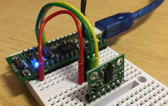
Vl6180x breakout board with tinyK20 (NXP Kinetis K20) microcontroller-board
VL6180X
STMicroelectronics calls its technology ‘FlightSense.’ It uses a SPAD (Single Photon Avalanche Diode) array and a VCSEL (Vertical Cavity Surface-Emitting Laser), combined with an ALS (Ambient Light Sensor) on the VL6180x. The ToF technology has been used in more and more applications: from gesture recognition and human presence detection in public transportation up to detecting and measuring object distances (e.g. how far a mobile phone is from the ear to adapt the audio volume).
The STMicroelectronics VL6180X sensor is a very small one. Its LGA package makes it a bit difficult to solder, at least with my SMD soldering skills (my students are by far better!). That’s why breakout modules from Pololu, Sparkfun, or Adafruit are a good starting point. Additionally, the VL6180X device is operating at 2.8V: the breakout modules include the necessary voltage generator and level shifter to use the module in 3.3V or 5V systems. The sensor uses IR light at 850 nm, and the VL6180X comes with an extra ALS (Ambient Light Sensor):

VL6180X close view
The sensor is specified for ranging up to 10 cm with a resolution of 1 mm, but I have found it works fine with the default settings and good conditions up to about 20 cm. There range scaling factor which can be used:
- 1: ranging up to 20 cm, 1 mm resolution
- 2: ranging up to 40 cm, 2 mm resolution
- 3: ranging up to 60 cm, 3 mm resolution
The range scaling is not mentioned in the data sheet, but mentioned in UM1876.
Wiring
Below a picture of the Pololu breakout module:

Vl6180x breakout board top side
The board has the following pins (left-to-right in the picture below):
- GPIO1: programmable interrupt output
- GPIO0/CE: Driving this pin low puts the sensor into standby mode. Otherwise, it can be used as programmable interrupt output of the sensor. The CE function is needed if multiple sensors are on the same I2C bus (more about this later)
- SCL: I2C clock
- SDA: I2C data
- GND: Ground
- VIN: supply voltage (2.7-5V)
- VDD: 2.8V regulator output

VL6180X breakout board bottom side
Wiring
Using a single sensor, only SCL, SDA, GND, and VIN are needed. Below is how I have wired it up with a tinyK20 microcontroller board:

VL6180X wiring
I2C Interface
To read and write, the device registers over I²C. I’m using the following routines with the GenericI2C (GI2C1) driver:
uint8_t VL_WriteReg8(uint8_t i2cDeviceAddress, uint16_t reg, uint8_t val) {
  uint8_t r[2];

  r[0] = reg>>8;
  r[1] = reg&0xff;
  return GI2C1_WriteAddress(i2cDeviceAddress, &r[0], sizeof(r), &val, sizeof(val));
}

uint8_t VL_WriteReg16(uint8_t i2cDeviceAddress, uint16_t reg, uint16_t val) {
  uint8_t r[2], v[2];

  r[0] = reg>>8;
  r[1] = reg&0xff;
  v[0] = val>>8;
  v[1] = val&0xff;
  return GI2C1_WriteAddress(i2cDeviceAddress, &r[0], sizeof(r), &v[0], sizeof(v));
}

uint8_t VL_ReadReg8(uint8_t i2cDeviceAddress, uint16_t reg, uint8_t *valP) {
  uint8_t tmp[2];

  tmp[0] = reg>>8;
  tmp[1] = reg&0xff;
  return GI2C1_ReadAddress(i2cDeviceAddress, &tmp[0], sizeof(tmp), valP, 1);
}

uint8_t VL_ReadReg16(uint8_t i2cDeviceAddress, uint16_t reg, uint16_t *valP) {
  uint8_t tmp[2];

  tmp[0] = reg>>8;
  tmp[1] = reg&0xff;
  return GI2C1_ReadAddress(i2cDeviceAddress, &tmp[0], sizeof(tmp), (uint8_t*)valP, 2);
}
Sensor Initialization
The sensors need a special initialization sequence, explained in AN4545 and DT0037:
/* Initialize sensor with settings from ST application note AN4545, section 9 -
   "Mandatory : private registers" */
uint8_t VL_InitDevice(uint8_t i2cDeviceAddress) {
  uint8_t res;

  res = VL_WriteReg8(i2cDeviceAddress, 0x207, 0x01);
  if (res!=ERR_OK) {
    VL_OnError(VL_ON_ERROR_INIT_DEVICE);
    return res;
  }
  res = VL_WriteReg8(i2cDeviceAddress, 0x208, 0x01);
  if (res!=ERR_OK) {
    VL_OnError(VL_ON_ERROR_INIT_DEVICE);
    return res;
  }
  res = VL_WriteReg8(i2cDeviceAddress, 0x096, 0x00);
  if (res!=ERR_OK) {
    VL_OnError(VL_ON_ERROR_INIT_DEVICE);
    return res;
  }
  res = VL_WriteReg8(i2cDeviceAddress, 0x097, 0xFD);
  if (res!=ERR_OK) {
    VL_OnError(VL_ON_ERROR_INIT_DEVICE);
    return res;
  }
  res = VL_WriteReg8(i2cDeviceAddress, 0x0E3, 0x00);
  if (res!=ERR_OK) {
    VL_OnError(VL_ON_ERROR_INIT_DEVICE);
    return res;
  }
  res = VL_WriteReg8(i2cDeviceAddress, 0x0E4, 0x04);
  if (res!=ERR_OK) {
    VL_OnError(VL_ON_ERROR_INIT_DEVICE);
    return res;
  }
  res = VL_WriteReg8(i2cDeviceAddress, 0x0E5, 0x02);
  if (res!=ERR_OK) {
    VL_OnError(VL_ON_ERROR_INIT_DEVICE);
    return res;
  }
  res = VL_WriteReg8(i2cDeviceAddress, 0x0E6, 0x01);
  if (res!=ERR_OK) {
    VL_OnError(VL_ON_ERROR_INIT_DEVICE);
    return res;
  }
  res = VL_WriteReg8(i2cDeviceAddress, 0x0E7, 0x03);
  if (res!=ERR_OK) {
    VL_OnError(VL_ON_ERROR_INIT_DEVICE);
    return res;
  }
  res = VL_WriteReg8(i2cDeviceAddress, 0x0F5, 0x02);
  if (res!=ERR_OK) {
    VL_OnError(VL_ON_ERROR_INIT_DEVICE);
    return res;
  }
  res = VL_WriteReg8(i2cDeviceAddress, 0x0D9, 0x05);
  if (res!=ERR_OK) {
    VL_OnError(VL_ON_ERROR_INIT_DEVICE);
    return res;
  }
  res = VL_WriteReg8(i2cDeviceAddress, 0x0DB, 0xCE);
  if (res!=ERR_OK) {
    VL_OnError(VL_ON_ERROR_INIT_DEVICE);
    return res;
  }
  res = VL_WriteReg8(i2cDeviceAddress, 0x0DC, 0x03);
  if (res!=ERR_OK) {
    VL_OnError(VL_ON_ERROR_INIT_DEVICE);
    return res;
  }
  res = VL_WriteReg8(i2cDeviceAddress, 0x0DD, 0xF8);
  if (res!=ERR_OK) {
    VL_OnError(VL_ON_ERROR_INIT_DEVICE);
    return res;
  }
  res = VL_WriteReg8(i2cDeviceAddress, 0x09F, 0x00);
  if (res!=ERR_OK) {
    VL_OnError(VL_ON_ERROR_INIT_DEVICE);
    return res;
  }
  res = VL_WriteReg8(i2cDeviceAddress, 0x0A3, 0x3C);
  if (res!=ERR_OK) {
    VL_OnError(VL_ON_ERROR_INIT_DEVICE);
    return res;
  }
  res = VL_WriteReg8(i2cDeviceAddress, 0x0B7, 0x00);
  if (res!=ERR_OK) {
    VL_OnError(VL_ON_ERROR_INIT_DEVICE);
    return res;
  }
  res = VL_WriteReg8(i2cDeviceAddress, 0x0BB, 0x3C);
  if (res!=ERR_OK) {
    VL_OnError(VL_ON_ERROR_INIT_DEVICE);
    return res;
  }
  res = VL_WriteReg8(i2cDeviceAddress, 0x0B2, 0x09);
  if (res!=ERR_OK) {
    VL_OnError(VL_ON_ERROR_INIT_DEVICE);
    return res;
  }
  res = VL_WriteReg8(i2cDeviceAddress, 0x0CA, 0x09);
  if (res!=ERR_OK) {
    VL_OnError(VL_ON_ERROR_INIT_DEVICE);
    return res;
  }
  res = VL_WriteReg8(i2cDeviceAddress, 0x198, 0x01);
  if (res!=ERR_OK) {
    VL_OnError(VL_ON_ERROR_INIT_DEVICE);
    return res;
  }
  res = VL_WriteReg8(i2cDeviceAddress, 0x1B0, 0x17);
  if (res!=ERR_OK) {
    VL_OnError(VL_ON_ERROR_INIT_DEVICE);
    return res;
  }
  res = VL_WriteReg8(i2cDeviceAddress, 0x1AD, 0x00);
  if (res!=ERR_OK) {
    VL_OnError(VL_ON_ERROR_INIT_DEVICE);
    return res;
  }
  res = VL_WriteReg8(i2cDeviceAddress, 0x0FF, 0x05);
  if (res!=ERR_OK) {
    VL_OnError(VL_ON_ERROR_INIT_DEVICE);
    return res;
  }
  res = VL_WriteReg8(i2cDeviceAddress, 0x100, 0x05);
  if (res!=ERR_OK) {
    VL_OnError(VL_ON_ERROR_INIT_DEVICE);
    return res;
  }
  res = VL_WriteReg8(i2cDeviceAddress, 0x199, 0x05);
  if (res!=ERR_OK) {
    VL_OnError(VL_ON_ERROR_INIT_DEVICE);
    return res;
  }
  res = VL_WriteReg8(i2cDeviceAddress, 0x1A6, 0x1B);
  if (res!=ERR_OK) {
    VL_OnError(VL_ON_ERROR_INIT_DEVICE);
    return res;
  }
  res = VL_WriteReg8(i2cDeviceAddress, 0x1AC, 0x3E);
  if (res!=ERR_OK) {
    VL_OnError(VL_ON_ERROR_INIT_DEVICE);
    return res;
  }
  res = VL_WriteReg8(i2cDeviceAddress, 0x1A7, 0x1F);
  if (res!=ERR_OK) {
    VL_OnError(VL_ON_ERROR_INIT_DEVICE);
    return res;
  }
  res = VL_WriteReg8(i2cDeviceAddress, 0x030, 0x00);
  if (res!=ERR_OK) {
    VL_OnError(VL_ON_ERROR_INIT_DEVICE);
    return res;
  }
  return ERR_OK;
}
Ranging
The sensor offers multiple modes (continuous and single shot). The easiest one is the single shot ranging. The function below stores the measured value the pointer passed to the function:
uint8_t VL_ReadRangeSingle(uint8_t i2cDeviceAddress, int16_t *rangeP) {
  uint8_t res;
  uint8_t val;

  VL_WriteReg8(i2cDeviceAddress, SYSRANGE__START, 0x01);
  res = readRangeContinuous(i2cDeviceAddress, &val);
  if (res!=ERR_OK) {
    *rangeP = -1;
    return res; /* error */
  }
  if (val>=0 && val<=255) {
    *rangeP = val; /* store value */
    return ERR_OK;
  }
  *rangeP = -2; /* error */
  return ERR_FAILED;
}
Because it takes some time until the result is ready, the function below waits until the result is ready:
static uint8_t readRangeContinuous(uint8_t i2cDeviceAddress, uint8_t *valP) {
  uint8_t range;
  uint8_t res, val;
  uint16_t timeoutMs = 100;

  *valP = 0; /* init */
  do { /* breaks */
   res = VL_ReadReg8(i2cDeviceAddress, RESULT__INTERRUPT_STATUS_GPIO, &val);
   if (res!=ERR_OK) {
     break;
   }
   if ((val&0x4)!=0) {
     break; /* 4: New Sample Ready threshold event */
   }
   if (timeoutMs==0) { /* timeout */
     break;
   }
   WAIT1_WaitOSms(1);
   timeoutMs--;
  } while(1);
  if (timeoutMs==0) {
    return ERR_NOTAVAIL; /* timeout */
  }

  res = VL_ReadReg8(i2cDeviceAddress, RESULT__RANGE_VAL, &range); /* read range in millimeters */
  if (res!=ERR_OK) {
    return res;
  }
  res = VL_WriteReg8(i2cDeviceAddress, SYSTEM__INTERRUPT_CLEAR, 0x01); /* clear interrupt flag */
  if (res!=ERR_OK) {
    return res;
  }
  *valP = range;
  return ERR_OK;
}
Reading Ambient Light Level
The same principle is used to read the ambient light level:
static uint8_t readAmbientContinuous(uint8_t i2cDeviceAddress, uint16_t *valP) {
  uint16_t ambient;
  uint8_t res, val;
  uint16_t timeoutMs = 100;

  *valP = 0; /* init */
  do {
   res = VL_ReadReg8(i2cDeviceAddress, RESULT__INTERRUPT_STATUS_GPIO, &val);
   if (res!=ERR_OK) {
     break;
   }
   if ((val&0x20)!=0) {
     break; /* new value available */
   }
   if (timeoutMs==0) { /* timeout */
     break;
   }
   WAIT1_WaitOSms(1);
   timeoutMs--;
  } while(1);
  if (timeoutMs==0) {
    return ERR_NOTAVAIL; /* timeout */
  }

  res = VL_ReadReg16(i2cDeviceAddress, RESULT__ALS_VAL, &ambient); /* read ambient value */
  if (res!=ERR_OK) {
    return res;
  }
  res = VL_WriteReg8(i2cDeviceAddress, SYSTEM__INTERRUPT_CLEAR, 0x02); /* clear interrupt flag */
  if (res!=ERR_OK) {
    return res;
  }

  *valP = ambient;
  return ERR_OK;
}

uint8_t VL_ReadAmbientSingle(uint8_t i2cDeviceAddress, uint16_t *ambientP) {
  VL_WriteReg8(i2cDeviceAddress, SYSALS__START, 0x01);
  return readAmbientContinuous(i2cDeviceAddress, ambientP);
}
Using Multiple Sensors
On the MINT Robot (see "MINTomat: World’s Most Complicated Bubble Gum Automata?") we are using multiple sensors:

Robot with sensors on each side

3D Printed cover with board
Because the sensors, by default, use the same I²C address, the sensors have to be enabled one after another while assigning different I²C device addresses. For this, the CE pin is used to enable one sensor after another. A GPIO pin (input/output, default after reset as the input pin) for each module is used:

ToF CE pin configuration
The code below demonstrates how to do this inside a FreeRTOS task:
#define VL_NOF_DEVICES  4
#define VL6180X_DEFAULT_I2C_ADDRESS 0x29 /* default address 0101001b (shifted on the bus it is 0101001x */

typedef struct {
  int16_t mm; /* distance in mm, negative values are error values */
  uint8_t i2cAddr; /* I2C device address */
} DIST_ToF_DeviceDesc;

static DIST_ToF_DeviceDesc ToFDevice[VL_NOF_DEVICES]; /* ToF sensor distance in millimeters */
static uint8_t InitToF(void) {
  uint8_t res;
  int i;

  /* initialize data structure */
  for(i=0;i<VL_NOF_DEVICES;i++) {
    ToFDevice[i].mm = 0;
    ToFDevice[i].i2cAddr = VL6180X_DEFAULT_I2C_ADDRESS+1+i; /* make sure they are *not* at the default address! */
  }
  /* disable all devices (CE pin LOW): we will bring them up later one by one.... */
  for(i=0;i<VL_NOF_DEVICES;i++) {
    (void)VL_ChipEnable(i, FALSE); /* disable device */
  }
  for(i=0;i<VL_NOF_DEVICES;i++) {
    (void)VL_ChipEnable(i, TRUE); /* enable device */
    vTaskDelay(pdMS_TO_TICKS(100)); /* give some time to get it enabled */
    res = VL_SetI2CDeviceAddress(i, ToFDevice[i].i2cAddr); /* set hardware I2C address */
    if (res!=ERR_OK) {
      CLS1_SendStr("ERROR: Failed set i2C address of TOF device: ", SHELL_GetStdio()->stdErr);
      CLS1_SendNum8u(i, SHELL_GetStdio()->stdErr);
      CLS1_SendStr("\r\n", SHELL_GetStdio()->stdErr);
      return res;
    }
  }
  /* at this time all devices are enabled (CE pin HIGH) and have unique I2C addresses */
  for(i=0;i<VL_NOF_DEVICES;i++) {
    res = VL_InitAndConfigureDevice(ToFDevice[i].i2cAddr);
    if (res!=ERR_OK) {
      CLS1_SendStr("ERROR: Failed init of TOF device: ", SHELL_GetStdio()->stdErr);
      CLS1_SendNum8u(i, SHELL_GetStdio()->stdErr);
      CLS1_SendStr("\r\n", SHELL_GetStdio()->stdErr);
      return res;
    }
  }
  return ERR_OK;
}

static void TofTask(void *param) {
  uint8_t res;
  int errCntr = 0;
  int i;
  bool initDevices = TRUE;

  (void)param;
  vTaskDelay(pdMS_TO_TICKS(100)); /* wait to give sensor time to power up */
  /* finished init, run the sensor task */
  for(;;) {
    if (initDevices) {
      do {
        res = InitToF();
        if (res!=ERR_OK) {
          CLS1_SendStr("ToF init failed, retry....!\r\n", SHELL_GetStdio()->stdErr);
          vTaskDelay(pdMS_TO_TICKS(1000));
        }
      } while (res!=ERR_OK);
      CLS1_SendStr("ToF enabled!\r\n", SHELL_GetStdio()->stdOut);
      initDevices = FALSE;
    }
    for(i=0;i<VL_NOF_DEVICES;i++) {
      int16_t range;

      range = 0;
      res = VL_ReadRangeSingle(ToFDevice[i].i2cAddr, &range);
      if (res!=ERR_OK) {
        CLS1_SendStr("ToF FAILED!\r\n", SHELL_GetStdio()->stdErr);
        errCntr++;
        GI2C1_Deinit();
        GI2C1_Init();
        initDevices = TRUE; /* re-init devices */
      }
      ToFDevice[i].mm = range;
    } /* for */
    vTaskDelay(pdMS_TO_TICKS(20));
  }
}
Example Application
An example project is available on GitHub. It is a simple bare-metal application which initializes the sensor and then reports the reading on the console/UART:
#include "Application.h"
#include "VL6180X.h"
#include "LED1.h"
#include "WAIT1.h"
#include "CLS1.h"

void APP_Start(void) {
  uint8_t val=0;
  int16_t range;
  uint8_t res;
  uint16_t ambient;
  CLS1_ConstStdIOType *io = CLS1_GetStdio();

  VL_Init(); /* initialize sensor driver */
  res = VL_InitAndConfigureDevice(VL6180X_DEFAULT_I2C_ADDRESS);
  if (res!=ERR_OK) {
    CLS1_SendStr("ERROR: Failed init of TOF device: ", io->stdErr);
    CLS1_SendNum8u(VL6180X_DEFAULT_I2C_ADDRESS, io->stdErr);
    CLS1_SendStr("\r\n", io->stdErr);
  }
  for(;;) {
    res = VL_ReadRangeSingle(VL6180X_DEFAULT_I2C_ADDRESS, &range);
    if (res!=ERR_OK) {
      CLS1_SendStr("ERROR Range: ", io->stdErr);
      CLS1_SendNum8u(res, io->stdErr);
    } else {
      CLS1_SendStr("Range: ", io->stdOut);
      CLS1_SendNum8u(range, io->stdOut);
    }
    res = VL_ReadAmbientSingle(VL6180X_DEFAULT_I2C_ADDRESS, &ambient);
    if (res!=ERR_OK) {
      CLS1_SendStr(" ERROR Ambient: ", io->stdErr);
      CLS1_SendNum8u(res, io->stdErr);
    } else {
      CLS1_SendStr(" Ambient: ", io->stdOut);
      CLS1_SendNum16u(ambient, io->stdOut);
    }
    CLS1_SendStr("\r\n", io->stdOut);
    LED1_Neg();
    WAIT1_Waitms(500);
  }
}
The output looks like this:

Application output
Summary
With the STMicroelectronics VL6180X, I’m able to measure very accurate distances for robotics and gesture recognition. The VL6180X works up to 60 cm — for longer distances, the VL53L0X (up to 2 m) should be considered.
An example project is available on GitHub.
Happy flying!
Published at DZone with permission of Erich Styger. See the original article here.
Opinions expressed by DZone contributors are their own.
Comments