MCUXpresso SDK Tutorial: Using I2C Driver on OKdo E1 Board
In an earlier tutorial I introduced using I2C with the NXP LPC55S69 on OKdo E1 board to read a Bosch BME280 environmental sensor on a Mikroe Weather Click bo...
Join the DZone community and get the full member experience.
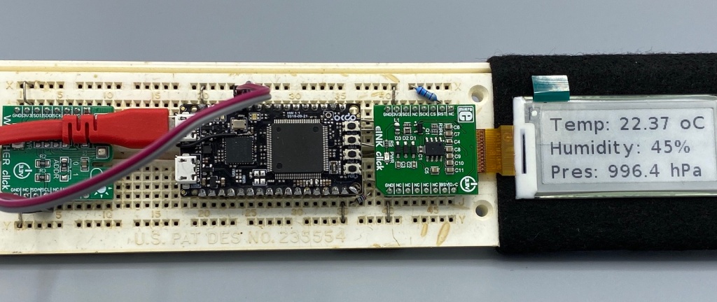
Join For FreeIn an earlier tutorial I introduced using I2C with the NXP LPC55S69 on OKdo E1 board to read a Bosch BME280 environmental sensor on a Mikroe Weather Click board. The MCUXpresso Clocks, Pins and Peripheral Config tools were used to get it running. It's all for my Weather Station project that I've been working on during these months of lockdown. It is starting to take shape - as you can see from the photograph:
Now I really need to start reading and writing to the BME280 sensor, and that means using the I2C driver in the lpcxpresso55s69 SDK. And so this week I'll provide a forensic examination of the most commonly-used I2C function call.
The software has been built up from a previous week. It's all here if you want to reproduce my steps. And note that I've placed all of the code into one big 'C' module (that is not great practice, but makes the download easier).
Looking at main() we can see that there are a number of steps to follow when reading from the sensor.
- Initialise the hardware (lines 593-601);
- Test I2C communication (line 603);
- Read BME280 Calibration data (line 604);
- Write BME280 Configuration parameters (oversampling rate, line 605);
- Trigger BME280 to make a conversion (line 609);
- Poll BME280 status register for IsMeasuring to be complete (610);
- Read raw BME280 Sensor data (Pressure, Temp, Humidity, line 611);
- Convert raw BME280 Sensor data into SI units (hPa, oC, %)(lines 612-614).

That is a number of steps, but these all require either reading or writing to the BME280 environmental sensor over I2C. I'm going to investigate the function I2C_WriteBME280ModeForce() as a case study, and it helps to first understand the registers implemented inside the BME280.

In total, there are 55 registers, and most of these are the cyan Calibration data registers. Bosch provide a detailed end-of-production-line calibration of the sensor, making it easy to convert the raw sensor data (from the yellow Data registers) once we have read out both the Calibration data and the Data registers. Before using the sensor it is necessary to configure the sensor by writing to the white Control registers, and then triggering a conversion by writing to the mode[1:0] bits in the register at address 0xF4. The BME280 has three operating modes (sleep, normal, forced) and my software uses the 'forced' mode to make a single sample of the three sensors. It takes several milliseconds for the BME280 to convert the analog sensor data into digital results, and the sensor sets a bit measuring in the purple Status register during this time. The software will force a conversion, and poll the measuring bit, waiting for the data to become available.
In order to trigger the conversion in forced mode, we need to write to the BME280 sensor, and set bit '0' in the ctrl_meas register. This is register number 0xF4. The I2C write physical interface looks like this:

First we output the 7-bit slave address ( 0x76) and signal that this is a by clearing the RW bit - bit 0. After the BME280 slave acknowledges the byte, we output the Register address ( 0xF4 in this case for ), again waiting for the acknowledgement from the BME280 sensor. Lastly we send the data to be written. Control register ctrl_meas contains three fields and we must be careful not to change the existing OverSample settings. Since the sensor is in mode '0b00' sleep and we want to transition into Forced mode, we write 0b01 into the mode[1:0] field, and the full data byte is value 0x25.

The main() routine calls the function I2C_WriteBME280ModeForce() at line 609 to output this I2C transaction:

The transaction is all handled by the SDK I2C driver function I2C_MasterTransferNonBlocking() at line 404. The three parameters are:
- the base address of the I2C peripheral (it is implemented in FLEXCOMM4_PERIPHERAL);
- the address of the I2C configuration handle (created at line 601, and configuring the callback);
- the address of the transfer structure masterTransfer.
Our code needs to define and populate the transfer structure, and you can see this being done in lines 395-402:
- is set to BME280-CTRL_MEAS, defined as 0x25;
- slaveAddress is set to BME280_ADDR, defined as 0x76;
- subaddress is set to BME280_CTRL_MEAS, defined as 0xF4;
- subaddressSize is 1, writing to one register;
- data is set to the address of writeData
- dataSize is 1, sending one byte of data;
- is set to kI2C_TransferDefaultFlag, making the transfer begin with a Start bit and end with a Stop bit.
Watching this "on the wire" and letting the I2C protocol analyzer do all the hard work, we see this:

It is easy to see the start and stop bits (SDA is active low, firstly with clock high, then low with a rising edge of SCL). In between are the three phases, starting with [W]0x76, then 0xF4 and lastly with 0x25. It is all behaving as expected.
The same basic approach can be taken with the other higher level function calls in the application - I2C_ReadBME280Data(), I2C_ReadBME280ConvertComplete() for example. In the case of a it is just necessary to declare the appropriate-size buffer for the data to be read from the sensor. Since there are 8 data registers, the define BME280_DATA_N is 8, and the registers start at address BME280_DATA_REG 0xF7.


After reading the data, calibrating according to the Bosch 'double-precison float' algorithm (from the BME280 datasheet, appendix A), I see the following data output from the Weather Station application:

At the time of writing the weather to the west of London UK is "changeable". It is dry and warm but we are changing from rainy weather to more settled weather. The atmospheric pressure has been rising, indicating a change from low pressure to high pressure.
As always, I've recorded a video of the tutorial, and it is hosted on my embeddedpro YouTube channel. It's embedded here, too:
Since reading the sensor just once does not make a lot of sense, I've posted an additional video showing how to set up the Real Time Clock (RTC) on the LPC55S69 and using the RTC driver in the lpcxpresso55s69 SDK. This video shows a 1 minute interrupt and will form the basis for the next tutorial in this series... where I'll start using the eInk display on the Weather Station.
Published at DZone with permission of Erich Styger. See the original article here.
Opinions expressed by DZone contributors are their own.
Comments