Sketching API Connections
Join the DZone community and get the full member experience.
Join For Freedaniel bryant , simon and i recently had a discussion about how to represent system communication with external apis. the requirement for integration with external apis is now extremely common but it's not immediately obvious how to clearly show them in architectural diagrams.
how to represent an external system?
the first thing we discussed was what symbol to use for a system supplying an api. traditionally, uml has used the actor (stick man) symbol to represent a "user or any other system that interacts with the subject" (uml superstructure specification, v2.1.2). therefore a system providing an api may look like this:

i've found that this symbol tends to confuse those who aren't well versed in uml as most people assume that the actor symbol always represents a *person* rather than a system. sometimes this is stereotyped to make it more obvious e.g.

however the symbol is very powerful and tends to overpower the stereotype. therefore i prefer to use a stereotyped box for an external system supplying an api. let's compare two context diagrams using boxes vs stick actors.
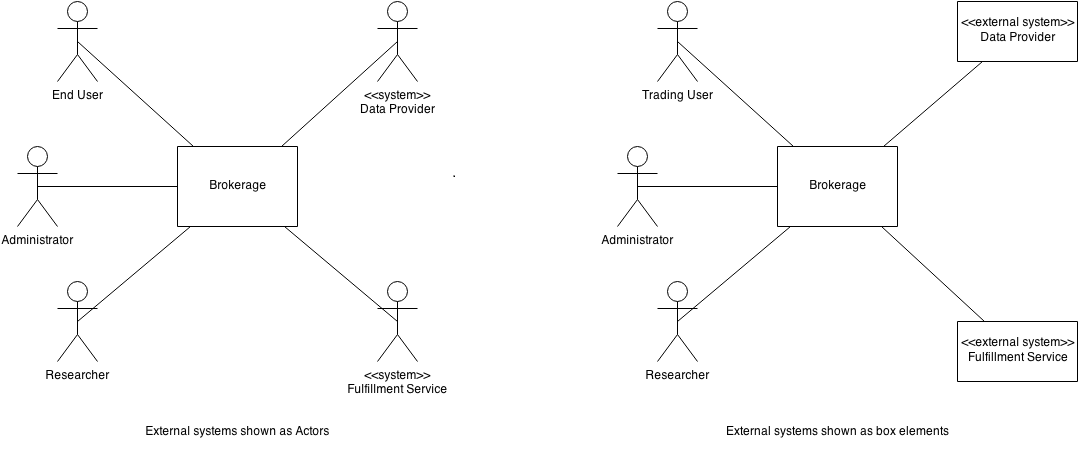
in which diagram is it more obvious what are systems or people?
note that archimate has a specific symbol for application service that can be used to represent an api:
 (application service notation from the open group's archimate 2.1 specification)
an api or the system that supplies it?
whatever symbol we choose, what we've done is to show the *system* rather than the actual api. the api is a definition of a service provided by the system in question. how should we provide more details about the api?
there are a number of ways we could do this but my preference is to give details of the api on the connector (line connecting two elements/boxes). in c4 the guidelines for a container diagram includes listing protocol information on the connector and an api can be viewed as the layer above the protocol. for example:
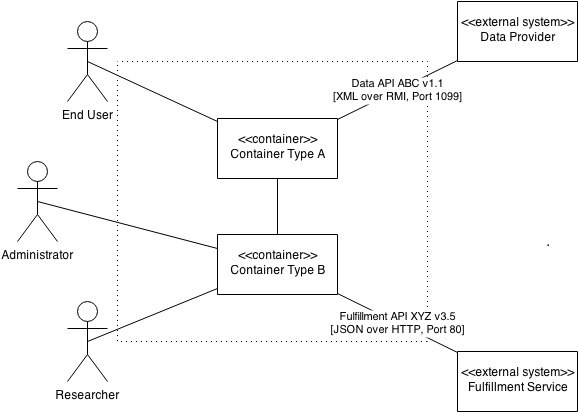
multiple apis per external system
many api providers supply multiple services/apis (i'm not referring to different operations within an api but multiple sets of operations in different apis, which may even use different underlying protocols.) for example a financial marketplace may have apis that do the following:
- allow a bulk, batch download of static data (such as details of companies listed on a stock market) via xml over http.
- supply real time, low latency updates of market prices via bespoke messages over udp.
- allow entry of trades via industry standard fpml over a queuing system.
- supply a bulk, batch download of trades for end-of-day reconciliation via fpml over http.
two of the services use the same protocol (xml over http) but have very different content and use. one of the apis is used to constantly supply information after user subscription (market data) and the last service involves the user supplying all the information with no acknowledgment (although it should reconcile at eod).
there are multiple ways of showing this. we could:
- have a single service element, list the apis on it and have all components linking to it.
- show each service/api as a separate box and connect the components that use the individual service to the relevant box.
- show a single service element with multiple connections. each connection is labeled and represents an api.
- use a port and connector style notation to represent each api from the service provider. provide a key for the ports.
- use a uml style 'cup and ball' notation to define interfaces and their usage.
some examples are below:
a single service element and simple description
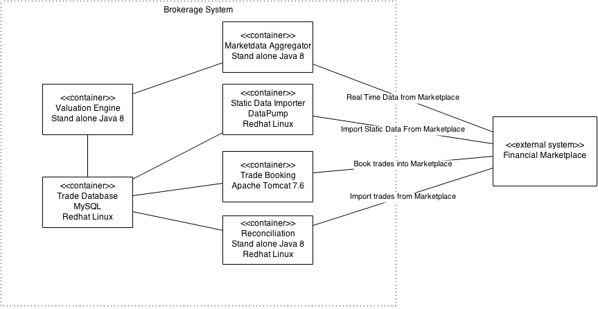
in the above diagram the containers are stating what they are using but contain no information about how to use the apis. we don't know if it is a single api (with different operations) or anything about the mechanisms used to transport the data. this isn't very useful for anyone implementing a solution or resolving operational issues.
single, service box with descriptive connectors
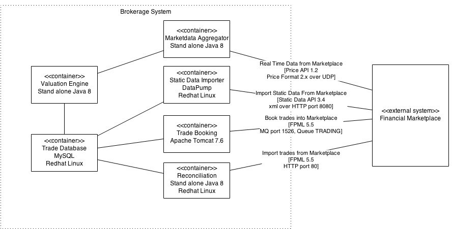
in this diagram there is a single, service box with descriptive connectors. the above diagram shows all the information so is much more useful as a diagnostic or implementation tool. however it does look quite crowded.
services/apis shown as separate boxes
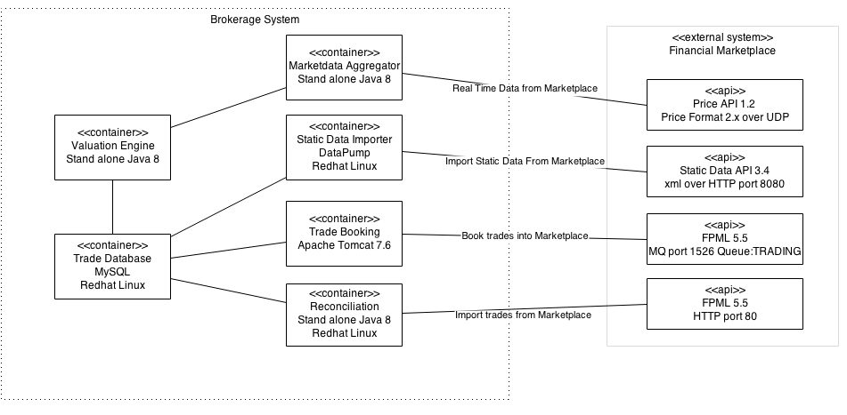
here the external system has its services/apis shown as separate boxes. this contains all the information but might be mistaken as defining the internal structure of the external system. we want to show the services it provides but we know nothing about the internal structure.
using ports to represent apis
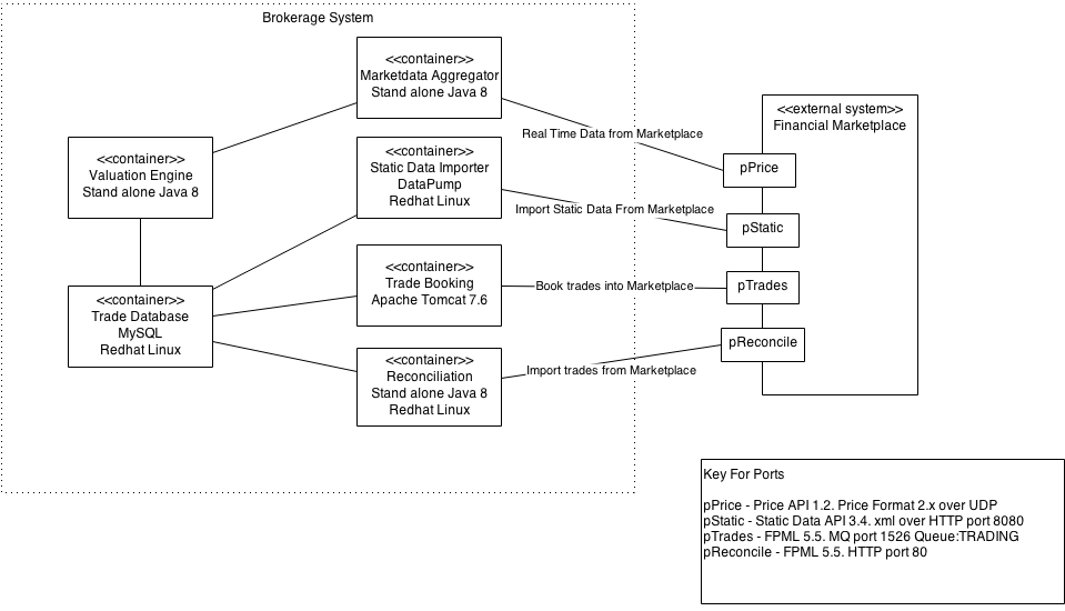
in the above diagram the services/apis are shown as 'ports' on the external system and the details have been moved into a separate key/table. this is less likely to be mistaken as showing any internal structure of the external service. (note that i could have also shown outgoing rports from the brokerage system.)
uml interfaces
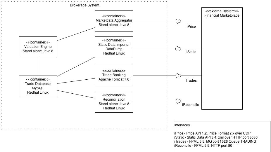
this final diagram is using a uml style interface provider and requirer. this is a clean diagram but requires the user to be aware of what the cup and ball means (although i could have explained this in the key).
conclusion
any of these solutions could be appropriate depending on the complexity of the api set you are trying to represent. i'd suggest starting with a simple representation (i.e. fully labeled connections) and moving to a more complex one if needed but remember to use a key to explain any elements you use!
Published at DZone with permission of Robert Annett, DZone MVB. See the original article here.
Opinions expressed by DZone contributors are their own.

Comments