World Stepper Clock With NXP LPC845
Learn more about building a stepper clock in this microcontroller tutorial!
Join the DZone community and get the full member experience.
Join For Free
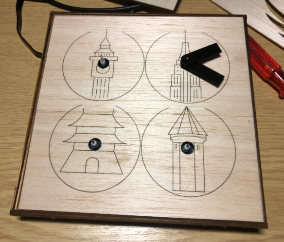
I really love clocks. I think this may be because I am living here in Switzerland. Besides that, clock projects are just fun! After I have completed my project building a single clock using stepper motors (see " DIY Stepper Motor Clock with NXP LPC845-BRK "), I wanted to build a special one that was able to show up in four different time zones. Below is an example of London (UK), New York (USA), Beijing (China), and Lucerne (Switzerland):

The clock is not only able to show time for up to four different locations on the world; using dual-shaft 360° stepper motors can show patterns beyond the time:
In that video, the minute hand incrementing is changed every two seconds to advance the time faster.
In that project, a microcontroller (NXP LPC845, ARM Cortex-M0) is driving 8 stepper motors, one clock uses two motors, each individually controlled. Because the motors are special 360° motors, the zero position is determined with a magnet and a hall sensor for each hand. Using a serial connection, the clock can be configured. Because the clock can be away from a host PC, the clock uses RS-485.
This time, the clock different concept than the one in "DIY Stepper Motor Clock with NXP LPC845-BRK": instead of normal stepper motors it motors, which are used behind the dashboard in cars. I evaluated different motors, and the VID28.12 dual shaft one was selected for this project. The motors have been tested first with an LPC845-BRK breakout board:

Below a short video showing the motor in action:
Each VID28.12 unit includes two stepper motors with a dual shaft. The motor can be easily disassembled and modified as needed (e.g. for 360° operation):

For 360° operation, the end stop has to be removed (e.g. with a sharp knife). Otherwise, the motor is available from the factory without the end stop (this is what I have ordered after the first test unit).
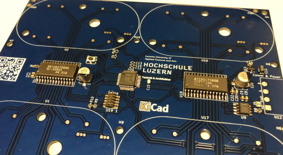
The PCB has been designed in KiCad:
- NXP LPC845 microcontroller
- 2 Switec X12.017 quad-stepper motor driver
- SWD debug port
- RS-485 interface
- 8 Hall sensors (AH3572)
- LED

The board has been produced by PCBWay. Below, the first board worked with a few patches.

Reflow
The board only has a few parts on the bottom (clock front) side. Most components are 0603, with the microcontroller using 0.5 mm pitch as the biggest challenge. Below, we have the first board placed in the reflow oven:

It came out pretty good, with some excess solder (expected) on the microcontroller pins:
Issues
There are many ways to mess up things. As a list of reminders for myself (and maybe everyone else, nobody is perfect!):
1) Carefully check the microcontroller pin alignment before getting it baked. It ended up soldered shifted by one pin.
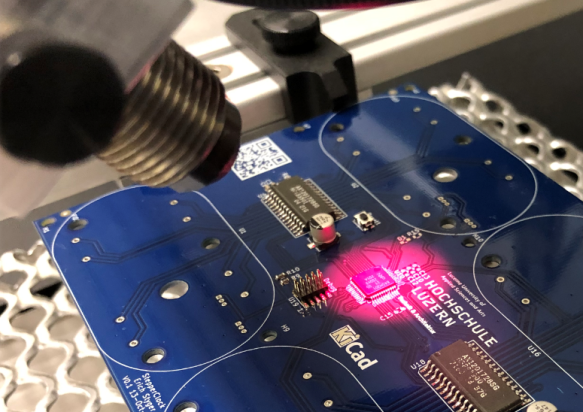
The image below shows excessive solder on the pin, which is on purpose and will be to be removed later.

Luckily, I had an infrared heater available in the lab to get it off and on the board again:
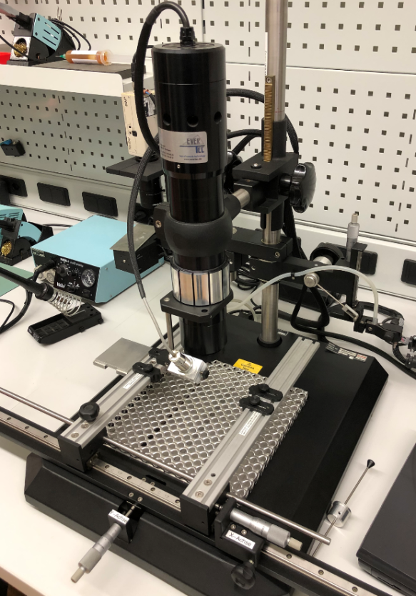
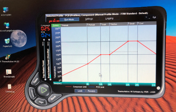
While the area (in red) is heated up, it gets monitored by a temperature sensor:
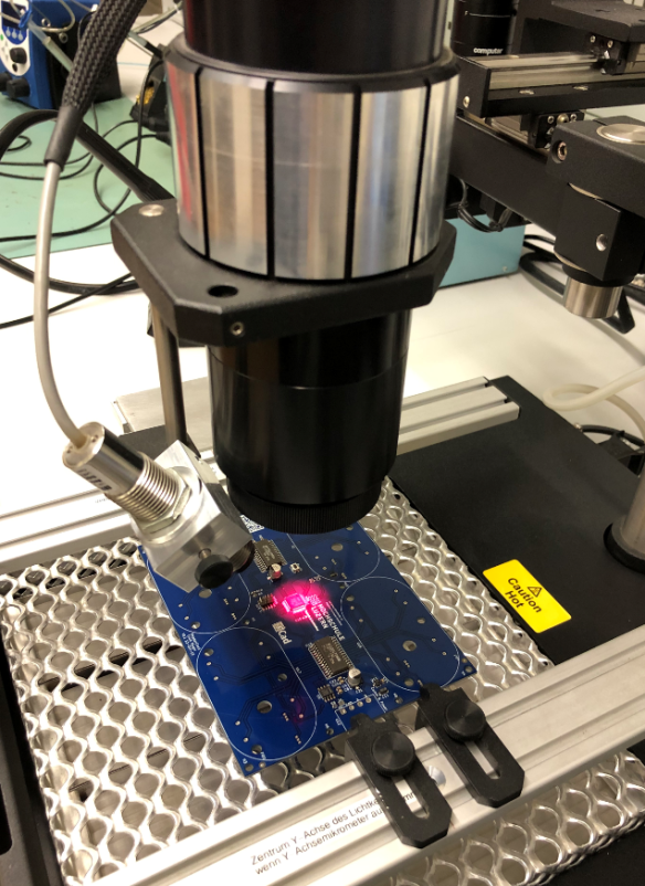

That way, I was able to get it off the board easily:

With the help of flux, solder wick, solder paste, and the heat gun, the LPC was placed correctly the second time.
2) Don’t miss adding solder paste to a pad. Otherwise, don’t wonder why a motor is not able to change direction:

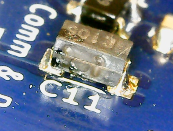
3) There is no ‘standard’ footprint and pin numbering for SOT-23 packages. Carefully, double-check the footprint and pin numbering used in the CAD tool. Or, be prepared for painful board ‘fixes’. Luckily, I had through-hole footprints added to the design as a backup.
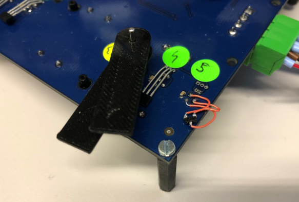
3) Carefully, check the marking and orientation of polarized capacitors. It is not a good idea to populate tantalum capacitors reversed. It might ‘work’ for a week or so. But it will end with magic smoke:
First Test Runs
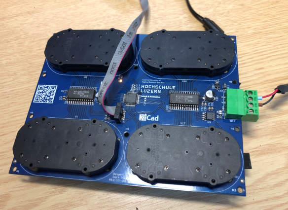
After populating the parts, it was time to develop the firmware. I added an SWD debug header on the board and used that to debug it with a SEGGER J-Link EDU Mini. The design includes RS-485 connector with 5V/GND so it can be powered from USB. I’m using a SparkFun USB-to-RS-485 converter board to connect it with the host PC to configure the board settings:

The first board assembled with motors and debug connector:
Below, the front of the board with an initial set of clock hands:

The video below shows one of the early tests with the motors:
Enclosure
The enclosure has been designed in Inkscape and then produced with a laser cutter. Below is the first version. The sides and back are made of laser-cut 4mm plywood. The front is using 1 mm balsa wood. That way, everything is inside 17x17x2 cm.
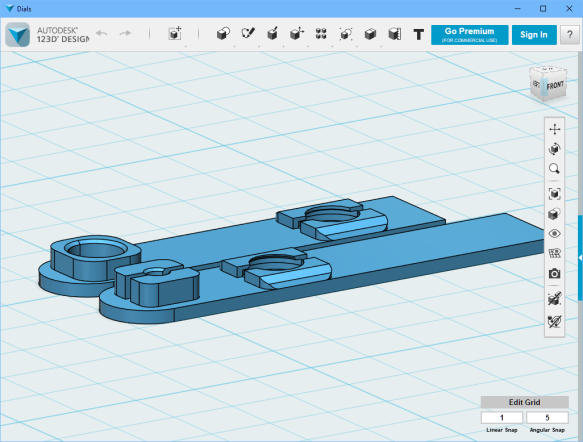
The hands for the clocks are 3D printed with PLA and include special sockets for the magnets on the bottom side of each hand:
Firmware
The firmware has been developed with the NXP MCUXpresso IDE V11.0.1 using the NXP MCUXpresso SDK and the McuLib.
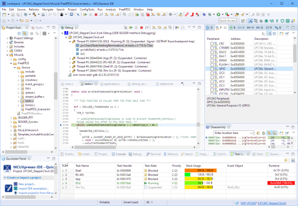
The firmware includes a command-line interface through the Segger RTT:

The same command-line interface can be used over the RS-485 connection too. Configuration data like the clock hand offsets or RS-485 device addresses are stored in the microcontroller flash at runtime if reconfigured.
Summary
The result of the project is a versatile world clock with four clocks make of automotive dashboard dual-shaft stepper motors. The clock is 17x17x2 cm in size and requires a 4-wire connection (5V, GND, A, B). It intentionally does not include a battery backed-up RTC (yet), as the idea is to connect multiple clocks to a bigger clock system. The clock can be used as a single clock; in that case, it gets configured through the RS-485 connection.
The design allows using custom front covers, for example, to show logos or landmarks for each time zone. For my first design, I used London, New York, Beijing, and Lucerne. The cover can be removed and replaced with a different one:
I plan to work on a new revision of the board. Until then, you can find the current firmware and design files on GitHub (see links below).
Happy Time-Zoning!
Resources
- NXP MCUXpresso IDE V11.0.1
- McuOnEclipse Library: https://github.com/ErichStyger/McuOnEclipseLibrary
- LPC845-BRK: Unboxing the NXP LPC845-BRK Board
- Stepper Clock project on GitHub: https://github.com/ErichStyger/mcuoneclipse/tree/master/Examples/MCUXpresso/LPC845-BRK/LPC845-BRK_StepperClock
- SparkFun RS-485-to-USB converter: https://www.sparkfun.com/products/9822
- World-Clock project on GitHub: https://github.com/ErichStyger/mcuoneclipse/tree/master/Examples/MCUXpresso/LPC845-BRK/LPC845-WorldClock
Published at DZone with permission of Erich Styger. See the original article here.
Opinions expressed by DZone contributors are their own.
Comments