Dependency Management
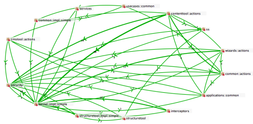
The large-scale design of a software system is manifested by its dependency structure. Only by explicitly managing dependencies over the complete software lifecycle is it possible to avoid the negative side effects of structural erosion. One important aspect of dependency management is to avoid cyclic compile-time dependencies between software components:
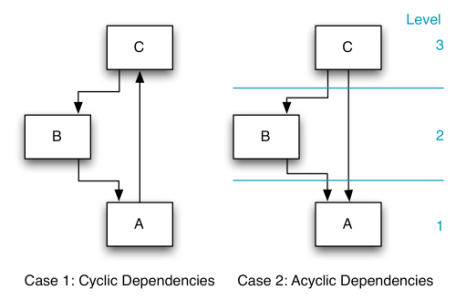
Case 1 shows a cyclic dependency between units A, B and C. Hence, it is not possible to assign level numbers to the units, leading to the following undesirable consequences:
- Understanding the functionality behind a unit is only possible by understanding all units.
- The test of a single unit implies the test of all units.
- Reuse is limited to only one alternative: to r ruse all units. This kind of tight coupling is one of the reasons why reuse of software components is hardly ever practiced.
- Fixing an error in one unit involves automatically the whole gr pup of the three units.
- An impact analysis of planned changes is difficult.
Case 2 represents three units forming an acyclic directed dependency graph. It is now possible to assign level numbers. The following effects are the consequences:
- A clear understanding of the units is achieved by having a clea r order, first A, then B and then C.
- A clear testing order is obvious: first test unit A; test continues with B and afterwards with C.
- In matter of reuse, it is possible to r ruse A isolated, A and B, or also the complete solution.
- To fix a problem in unit A, it can be tested in isolation, where eby the test verifies that the error is actually repaired. For testing unit B, only units B and A are needed. Subsequently, real integration tests can be done.
- An impact analysis can easily be done.
Please keep in mind that this is a very simple example. Many software systems have hundreds of units. The more units you have, the more important it becomes to be able to levelize the dependency graph. Otherwise, maintenance becomes a nightmare.

Here is what recognized software architecture experts say about dependency management:
“It is the dependency architecture that is degrading, and with it the ability of the software to be maintained.” [ASD]
“The dependencies between packages must not form cycles.” [ASD]
“Guideline: No Cycles between Packages. If a group of packages have cyclic dependencies then they may need to be treated as one larger package in terms of a release unit. This is undesirable because releasing larger packages (or package aggregates) increases the likelihood of affecting something.” [AUP]
“Cyclic physical dependencies among components inhibit understanding, testing and reuse.” [LSD]
Coupling Metrics
Another important goal of dependency management is to minimize the overall coupling between different parts of the software. Lower coupling means higher flexibility, better testability, better maintainability and better comprehensibility. Moreover, lower coupling also means that changes only affect a smaller part of an application, which greatly reduces the probability for regression bugs.
To control coupling, it is necessary to measure it. [LSD] describes two useful coupling metrics. Average Component Dependency (ACD) is telling us on how many components a randomly picked component will depend upon on average (including itself). Normalized Cumulative Component Dependency (NCCD) is comparing the coupling of a dependency graph (application) with the coupling of a balanced binary tree.
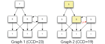
Above, you see two dependency graphs. The numbers inside of the components reflect the number of components reachable from the given component (including itself). The value is called Component Dependency (CD). If you add up all the numbers in the Graph 1 the sum is 23. This value is called “Cumulative Component Dependency” (CCD). If you divide CCD by the number of components in the graph, you get ACD. For Graph 1, this value would be 3.29.
Please note that Graph 1 contains a cyclic dependency. In Graph 2, removing the dependency shown in red has broken the cycle, which reduces the CCD to 19 and ACD to 2.71. As you can see, breaking cycles definitely helps to achieve our second goal, which is the overall reduction of coupling.
NCCD is calculated by dividing the CCD value of a dependency graph through the CCD value of a balanced binary tree with the same number of nodes. Its advantage over ACD is that the metric value does not need to be put in relation to the number of nodes in the graph. An ACD of 50 is high for a system with 100 elements but quite low for a system with 1,000 elements.
Detecting and Breaking Cyclic Dependencies
Agreeing that it is a good idea to avoid cyclic compile-time dependencies is one thing. Finding and breaking them is another story.
The only real option to find them is to use a dependency analysis tool. For Java, there is a simple free tool called “JDepend” [JDP]. If your project is not very big, you can also use the free “Community Edition” of “SonarJ” [SON], which is much more powerful than JDepend. For bigger pr objects you need to buy a commercial license of SonarJ. If you are not using Java or look for more sophisticated features like cycle visualization and breakup proposals, you will have to look at commercial tools.
After having found a cyclic dependency, you have to decide how to break it. Code refactorings can break any cyclic compile-time dependency between components. The most frequently used refactoring to do that is the addition of an interface. The following example shows an undesirable cyclic dependency between the “UI” component and the “Model” component of an application:
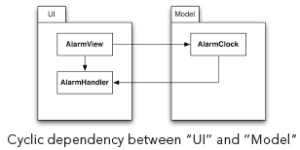
The example above shows a cyclic dependency between “UI” and “Model”.Now it is not possible to compile, use, test or understand the “Model” component without also having access to the “UI” component. Note that even though there is a cyclic dependency on the component level, there is no cyclic dependency on the type level.
Adding the interface “IAlarmHander” to the “Model” component solves the problem, as shown in the next diagram:
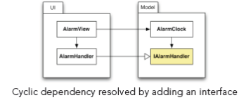
Now, the class “AlarmHandler” simply implements the interface defined in the “Model” component. The direction of the dependency is inverted by replacing a “uses” dependency with an inverted “implements” dependency. That is why this technique is also called the “dependency inversion principle”, first described by Robert C. Martin [ASD]. Now, it is possible to compile, test and comprehend the “Model” component in isolation. Moreover, it is possible to reuse the component by just implementing the “IAlarmHandler” interface. Please note that even if this method works pretty well most of the time, the overuse of interfaces and callbacks can also have undesirable side effects like added complexity. Therefore, the next example shows another way to break cycles. In [LSD], you will find several additional programming techniques to break cyclic dependencies.

In C++, you can mimic interfaces by writing a class that contains pure virtual functions only.
Sometimes, you can break cycles by rearranging features of classes. The following diagram shows a typical case:
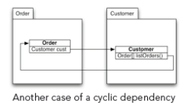
The “Order” class references the “Customer” class. The “Customer” class also references the “Order” class over the return value of a convenience method “listOr ders()”. Since both classes are in different packages, this creates an undesirable cyclic package dependency.
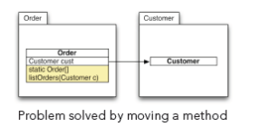
The problem is solved by moving the convenience method to the “Order” class (while converting it into a static method). In situations like this, it is helpful to levelize the components involved in the cycle. In the example, it is quite natural to assume that an order is a higher-level object than a customer. Orders need to know the customer, but customers do not need orders. As soon as levels are established, you simply need to cut all dependencies from lower-level objects to higher level objects. In our example, that is the dependency from “Customer” to “Order”.
It is important to mention that we do not look at runtime (dynamic) dependencies here. For the purpose of lar ge-scale system design, only compile-time (static) dependencies are relevant.

The usage of Inversion of Control (IOC) frameworks like the Spring Framework [SPG] will make it much easier to avoid cyclic dependencies and to reduce coupling.
Logical Architecture
Actively managing dependencies requires the definition of a logical architecture for a software system. A logical architecture groups the physical (programming language) level elements like classes, interfaces or packages (directories or name spaces in C# and C++) into higher-level architectural artifacts like layers, subsystems or vertical slices.
A logical architecture defines those artifacts, the mapping of physical elements (types, packages, etc.) to those artifacts and the allowed and forbidden dependencies between the architectural artifacts.
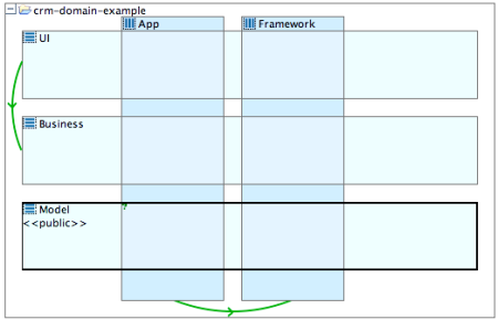
Example of a logical architecture with layers and slices
Here is a list of architectural artifacts you can use to describe the logical architecture of your application:
| Layer |
You cut your application into horizontal slices (layers) by using technical criteria. Typical layer names would be “User Interface”, “Service”, “DAO”, etc. |
| Vertical slice |
While many applications use horizontal layering, most software architects neglect the clear definition of vertical slices. Functional aspects should determine the vertical organization of your application. Typical slice names would be “Customer”, “Contract”, “Framework”, etc. |
| Subsystem |
A subsystem is the smallest of the architectural artifacts. It groups together all types implementing a specific mostly technical functionality. Typical subsystem names would be “Logging”, “Authentication”, etc. Subsystems can be nested in layers and slices. |
| Natural Subsystem |
The intersection between a layer and a slice is called a natural subsystem. |
| Subproject |
Sometimes projects can be grouped into several inter-relatsub projectscts. Subprojects are useful to organize a large project on the highest level of abstraction. It is recommended not to have more than seven to stub projectscts in a project. |
You can nest layers and slices, if necessary. However, for reasons of simplicity, it is not recommended using more than one level of nesting.
You can nest layers and slices, if necessary. However, for reasons of simplicity, it is not recommended using more than one level of nesting.
Mapping of code to architectural artifacts
To simplify code navigation and the mapping of physical entities (types, classes, packages) to architectural artifacts, it is highly recommended to use a strict naming convention for packages (namespaces or directories in C++ or C#). A proven best practice is to embed the name of architectural artifacts in the package name.
For example, you could use the following naming convention:
Parts in square brackets are optional. For subsystems not belonging to any layer or slice, you can use:
Of course, you need to adapt this naming convention if you use nesting of layers or slices.

Dangerous Attitude: “If it ain’t broken, don’t fix it!” Critics of dependency and quality management usually use the above statement to portray active dependency and quality management as a waste of time and money. Their argumentation is that there is no immediate benefit in spending time and resources to fix rule violations just for improving the inner quality of an application. It is hard to argue against that if you have a very short-time horizon. But if you expand the time horizon to the lifetime of an application, technical quality is the most important factor driving developer productivity and maintenance cost. This shortsighted thinking is one of the major reasons why so many medium- to large-scale applications are so hard to maintain. Many costly project failures can also be clearly associated with lack of technical quality.
Application Security Aspects
Most people don’t think about the connection between application security and the architecture (dependency structure) of an application. But experience shows that potential security vulnerabilities are much more frequent in applications that suffer from structural erosion. The reason for that is quite obvious: if the dependency structure is broken and full of cycles, it is much harder to follow the flow of tainted data (un-trusted data coming from the outside) inside of the application. Therefore, it is also much harder to verify whether or not these data have been properly validated before they are being processed by the application.
On the other hand, if your application has a well-defined logical architecture that is reflected by the code, you can combine architectural and security aspects by designating architectural elements as safe or unsafe. “Safe” means that no tainted data are allowed within this particular artifact. “Unsafe” means that data flowing through the artifact is potentially tainted. To make an element safe, you need to ensure two things:
- The safe element should not call any API’s that return potentially tainted data (IO, database access, HTTP session access etc.). I f this should be necessary for any reason all data returned by those API’s must be validated.
- All entry points must be pr otected by data validation.
This is much easier to check and enforce (with a dependency management tool) than having to assume that the whole code base is potentially unsafe. The dependency management tool plays an important role in ensuring the safety of an element by verifying that all incoming dependencies only use the official entry points. Incoming dependencies bypassing those entry points would be marked as violations.
Of course, the actual data processing should only be done in “safe” architectural elements. Typically, you would consider the Web layer as “unsafe”, while the layers containing the business logic should all be “safe” layers.
Since many applications are suffering from more or less severe structural erosion, it is quite difficult to harden them against potential security threats. In that case, you can either try to reduce the structural erosion and create a “safe” processing kernel using a dependency management tool or rely on expensive commercial software security analysis tools specialized on finding potential vulnerabilities. While the first approach will cost you more time and effort in the short term, it will pay off nicely by actually improving the maintainability and security of the code. The second approach is more like a short-term patch that does not resolve the underlying cause, which is the structural erosion of the code base.


