Programming Embedded Systems the Easy Way — With State Machines
This article will give you an introduction to programming with state machines with a focus on graphical design tools.
Join the DZone community and get the full member experience.
Join For FreeMost embedded systems are reactive by nature. They measure certain properties of their environment with sensors and react to changes. For example, they display something, move a motor, or send a notification to another system. A reactive system is best represented by a state machine — a system that is always in one of a finite and well-defined set of possible states.
Programming finite-state machines manually can become an overwhelming task and produce results that are convoluted and hard to maintain. Graphical design tools help you to keep track of all the possible states and actions of your system. This article will give you an introduction to programming with state machines with a focus on graphical design tools. Furthermore, you will learn how to integrate the generated platform-independent code with the custom hardware-specific code to interact with the hardware — in this case, an Arduino board.
State machines are an ideal paradigm for developing reactive systems. The most significant characteristic of these reactive systems is that they interact with their environment using sensors and actuators. Examples for sensors are motion, brightness, or temperature sensors. Commonly used actuators include LEDs, displays, valves, and motors. Another important characteristic of these systems is that they have a finite set of possible states and that they are always in exactly one of those, which can be easily realized using state machines.
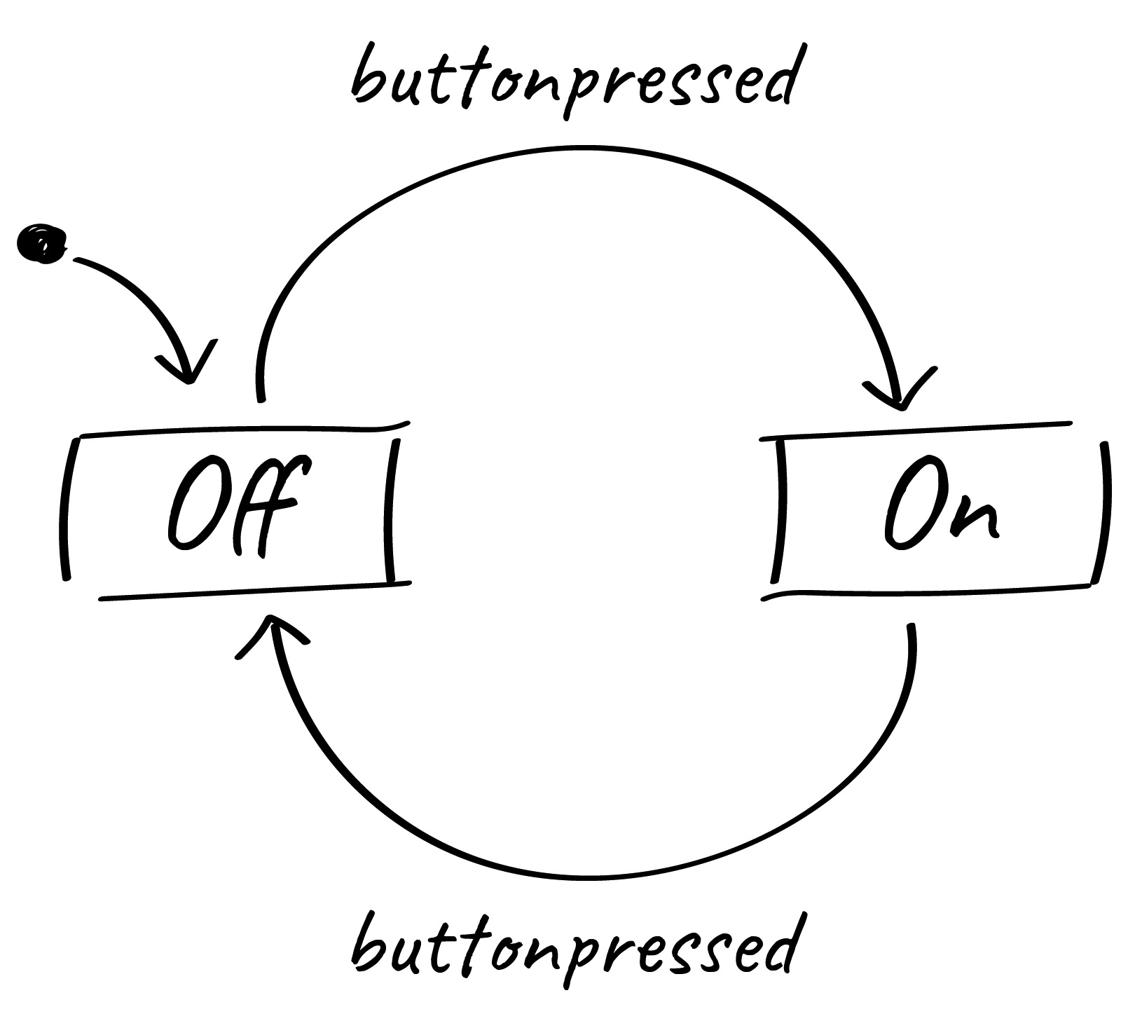
The possibly simplest example for a state machine with practical significance is a light switch control, as shown in Figure 1. Unsurprisingly, it has two states — On and Off. Only one of both states can be active at the same time. A change of one state to the next happens when a so-called transition is taken. In this example, this happens every time the buttonpressed event is raised.
Drawing your system with all its states can help you plan and get a clear view of your system’s expected behavior in different situations. You can then use that diagram as a blueprint to base source code and tests on. However, if the code is changed later, as is often the case, and the diagram is not, both diverge.
If someone then tries to develop tests based on the now outdated diagram, they will fail. It can become a huge problem if a model is used just for specification or documentation. Therefore, the diagram should not be only the blueprint of the code, it should be the code.
If you have already drawn the diagram, why write the code yourself? All the required logic is already specified in the diagram. Transforming the diagram into equivalent source code in, say, Java or C is just a mechanical task that could be performed by a machine. Using the diagram as the single source of truth and generating code from it automatically, is called the model-driven approach. However, to make use of this principle, a simple drawing board will not do.
Instead, you should use a proper modeling tool like YAKINDU Statechart Tools to draw the state diagram (statechart). Diagrams created with such a tool are easy to grasp. They improve communication between software developers and domain experts. Furthermore, unlike a diagram on a piece of paper or in a drawing application, modeling tools have a formal understanding of what a state machine is.
This enables them (and you) to simulate and test their behavior — without even writing a single line of code. The models themselves are platform-independent, so you can generate source code in any language you like from them. Tools typically support C, C++, Java, and Python.
If you are still unsure how model-driven software development works, do not worry — we will now explore it by example. We will use statecharts and code generation to develop a very simple automated light with a few inputs and outputs.
Our example: automated and motion-activated lights
The task of an automatic illumination is rather simple: There should be light only when it’s dark, but it should not waste energy while no one is around. To accomplish this, most staircase lights are controlled by a timer. By pushing a button, the light is activated, and after a certain time, it is automatically switched off again. However, that would be rather boring as a statechart example, so for this article, we spiced it up a little by incorporating an additional mode that is driven by a motion sensor.
The light should have three possible operation modes:
- Permanently off
- On — with time-controlled switch-off
- Automatic — with motion sensor
A button allows the user to cycle through these modes. Two LEDs display the currently selected operation mode.
From these specifications, you can derive the basic structure of the state machine pretty easily, as shown in Figure 2:
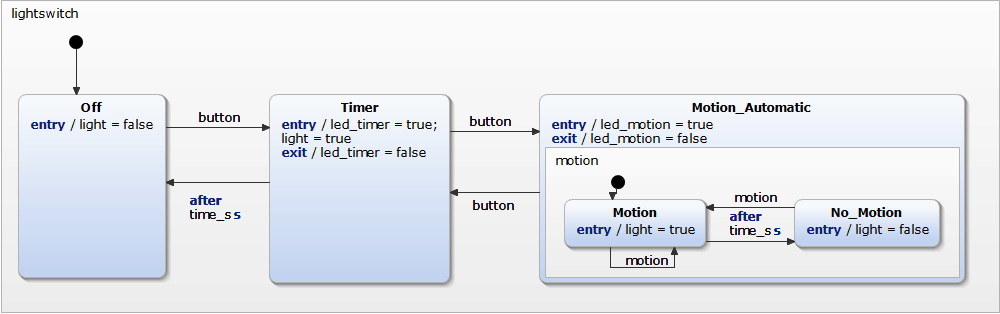
A change between the Off, Timer, and Motion_Automatic states are triggered by events — either by pushing a button or after a timer expires. If the user presses the button once, the timer mode is activated, the light goes on and switches off automatically after 30 seconds. If the user presses the button again before the 30 seconds run out, the motion sensor mode is activated.
Whenever the motion sensor detects someone (or something) moving, the light is switched on, if needed, for another 30 seconds. The timer is reset each time a motion is detected. The two LEDs indicating the current mode are activated and deactivated as needed when entering or exiting their respective states. This way, the whole controller logic is completely encapsulated within the state machine, also known as the automaton.
If the automaton is meant to run on an embedded system, we can now generate C or C++ code directly from the diagram. The generated code contains all the logic from the model. Only the code that interfaces with the actual hardware needs to be written manually.
In this example, this encompasses raising the button event when the actual button is pressed, controlling the actual staircase light, and controlling the status LEDs. This manual programming is needed because the generated code is independent of the target platform. The same holds for the timers — the time is handled very differently on different target platforms.
There are many possible ways to implement a state machine. Methods that are used most often are state tables, switch-case based constructs or — often used in object-oriented programming languages — the state pattern. If you want to read more in-depth information about this topic, you can find an extensive comparison of this whitepaper. By default, YAKINDU Statechart Tools generates state machine code using switch-case statements. This ensures a good performance while still maintaining good readability of the source code.
How the Generated Code Works
As mentioned above, the state machine code is realized as a switch-case statement. The main part of the execution will be handled in the runCycle function:
void Lightswitch::runCycle() {
clearOutEvents();
for (stateConfVectorPosition = 0; stateConfVectorPosition
< maxOrthogonalStates; stateConfVectorPosition++) {
switch (stateConfVector[stateConfVectorPosition]) {
case lightswitch_Off : {
lightswitch_Off_react(true); break;
}
case lightswitch_Timer : {
lightswitch_Timer_react(true); break;
}
case lightswitch_Motion_Automatic_motion_Motion : {
lightswitch_Motion_Automatic_motion_Motion_react(true);
break;
}
case lightswitch_Motion_Automatic_motion_No_Motion : {
lightswitch_Motion_Automatic_motion_No_Motion_react(true);
break;
}
default: break;
}
}
clearInEvents();
}
The runCycle function will be called whenever an event is raised. It iterates over all orthogonal states to do whatever is to be done there. A switch-case statement decides which function to call to execute the corresponding state reaction. For example, the Off state has one entry reaction, setting the light variable to false, which will only be executed when entering the state. It has one outgoing and one incoming transition. If the button event is raised, the state will be exited. This behavior is handled in the lightswitch_Off_react function:
xxxxxxxxxx
sc_boolean Lightswitch::lightswitch_Off_react(const sc_boolean
try_transition)
{
sc_boolean did_transition = try_transition;
if (try_transition) {
if (iface.button_raised) {
exseq_lightswitch_Off();
enseq_lightswitch_Timer_default();
react();
} else {
did_transition = false;
}
}
if ((did_transition) == (false)) {
did_transition = react();
}
return did_transition;
}
Let’s say the Off state has already been entered. Each time the runCycle function is called, it must check, whether the button event has been raised or not. This is done in the lightswitch_Off_react function. If the button event has indeed been raised, two things must be done: executing the exit sequence of the current state and executing the enter sequence of the target state:
xxxxxxxxxx
if (iface.button_raised) {
exseq_lightswitch_Off(); enseq_lightswitch_Timer_default();
react();
}
Implementation on an Arduino Uno
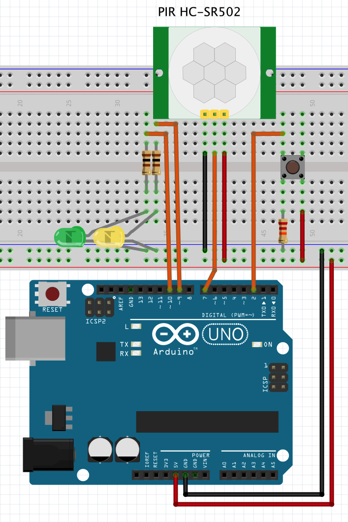
The software consists of two core components: the C++ code generated from the statechart and the handwritten glue code to connect the platform-independent state machine logic with the hardware.
The code generator creates the interface of the state machine, based on the events and variables defined in the model: void raise_button(); void raise_motion(); sc_boolean get_light() const; sc_boolean get_led_timer() const; sc_boolean get_led_motion() const; void init(); void enter();
For interfacing the state machine, an object of the particular state machine type must be defined, here: Lightswitch. This object represents the actual state machine and can be used to programmatically interact with the latter. For example:
xxxxxxxxxx
Lightswitch lightswitch;
int main(){
lightswitch.init();
lightswitch.enter();
lightswitch.raise_button();
}
With this simple implementation, the lightswitch state machine will be initialized, entered, and the button event will be raised. This, of course, is not the way to go. The goal is to connect the hardware (in this case the Arduino with the connected LEDs, sensor, and button) to the state machine. To do so, we will use the state machine in a very simple input-process-output pattern. This describes a simple loop as follows:
- Check the hardware and sensors for changes
- Transfer this information into the inputs of the state machine
- Let the state machine process these inputs
- Check the state machine’s outputs and react to them.
At first, the timer is refreshed with the current time. On an Arduino, we use the millis function to get the number of elapsed milliseconds since the system has been started. If needed, the timer will trigger time events in the state machine.
xxxxxxxxxx
long now = millis();
if(now - time_ms > 0) {
timerInterface->proceed(now - time_ms);
time_ms = millis();
}
Based on other inputs like button presses or motion detections, we can raise the “in” events of the state machine. Here, we don’t have to care about the mode the state machine is currently in — the generated state machine code encapsulates all that logic. We just raise the event and leave it to the state machine to decide whether it wants to react to it or not.
xxxxxxxxxx
// handle button press from ISR
if(buttonPressed) {
lightswitch.raise_button();
buttonPressed = false;
}
// read out motion sensor
if(digitalRead(7)) {
lightswitch.raise_motion();
}
After having processed all “in” events, the state machine has set the boolean variables properly. We can use them to control the “stair light” and the indicator LEDs.
xxxxxxxxxx
// set light
digitalWrite(13, lightswitch.get_light());
// set mode LEDs
digitalWrite(9, lightswitch.get_led_timer());
digitalWrite(10, lightswitch.get_led_motion());
In the end, we will put the Arduino into sleep mode if it is in the Off state, to save some energy. If the user presses the button, its interrupt service routine will be called, and the Arduino wakes up again. Please note that the timer that updates the value returned by millis is not updated while in sleep mode. Software timers relying on millis will therefore not be updated while in sleep mode. In this example, no timers are running while the Off state is active, so we can safely go to sleep.
xxxxxxxxxx
// if in Off-state, go to sleep (wake up by ISR) if(lightswitch.isStateActive(Lightswitch::lightswitch_Off)) {
enterSleep();
}
Flashing the Arduino is done with the usual Arduino IDE. To do this, we import the project containing the state machine as a library and manually write only the Arduino-specific code shown above in the Arduino IDE.
Conclusion
This example clearly shows the advantages of using models, like statecharts, in software development. The main advantages are:
- State machines are formal enough to be executable.
- Statecharts are graphical and easy to understand.
- Execution logic of a device and the associated hardware-related code are perfectly decoupled.
- Decoupling of hardware and device logic improves portability and reduces efforts needed for changes or further versions.
- They can be developed separately from each other.
This example can be extended and provides a perfect playground for experiments with state machines. You can find it in the repository of YAKINDU Statechart Tools.
Published at DZone with permission of Robin Herrmann. See the original article here.
Opinions expressed by DZone contributors are their own.
Comments