How to Build Your Own Arduino Thermostat
Want to learn how to build your own thermostat? Check out this post on how to use the Arduino to build your own thermostat using wiring methods and C++ code.
Join the DZone community and get the full member experience.
Join For FreeIf you are looking for information about how a thermostat works and how you can build your own DIY Arduino Thermostat, you are at the right place, keep reading or bookmark this page for later!
Before I start, I should say that I have been postponing this post for quite some time. The main reason is that you can't write a tutorial on how to create an Arduino Thermostat, because every HVAC unit is slightly different. For that reason, I have decided to explain how I built mine hoping that some people might get some inspiration out of it.
What Will You Find Here?
- Basic understanding of what is a thermostat and how it works
- Different examples of thermostat wiring diagrams
- How to reverse engineer your own thermostat
- How I built my DIY Arduino Thermostat
Before we get into the details on how you can approach building a DIY Arduino Thermostat, I want to walk you through the basics of the different types of thermostats and how do they work, if this is too basic for you, skip to the building part.
Thermostat Definition
I know this is very to basic, but I needed to start somewhere. In general terms, a thermostat is a device that senses the temperature and takes action to elevate or decrease it until it is as close as possible to the setpoint or target temperature. Although this post will only focus on HVAC machines, there are tons of systems that require a thermostat, including a water heater, oven, etc.
In case you didn't know (I didn't), HVAC stands for Heating, Ventilation, and Air Conditioning. In this post, I will explain to you how to have basic control over your HVAC system (if you have one) using an Arduino.
Thermostat Vs Thermometer
You may know this, but since some people asked me about it, I am going to provide a brief comparison between a thermostat and a thermometer.
The main difference is that a thermometer only senses the temperature and provides information — it doesn't take an action to affect the ambient temperature. A thermostat, on the flip side, not only monitors the temperature, but it is also able to regulate machines, like your central heating system.
Different Types of Thermostats
Let's talk about the different types of thermostat from two points of view — the wiring and the functionality that they offer.
Wiring
There are several types of thermostats. In this section, I will talk about the most popular ones and give you some tips on how to identify them.
Line-Voltage Thermostats
This type of thermostat is generally used for single heating systems, like baseboards or radiant systems. The way they work is actually pretty simple. The thermostat is connected in a series with the heating system, and when the device reaches the setpoint temperature, it stops the current from flowing through the thermostat. These type of systems are generally connected to 240V, so be careful if you decide to manipulate it — not that 120V can't get you in trouble...
Low-Voltage Thermostats
Nowadays, the low-voltage thermostat is the most common option for home installations. You will find them controlling all sorts of central heating systems that use oil, gas, or electricity. This type of thermostat has several advantages over the line-voltage type:
- They are more efficient in the way they handle the flow of current.
- The operating voltage is between 24v and 50v, hence, reducing the exposure to higher voltages. That is the reason that you see that the cables inside the thermostat are not as thick as the first type.
- There are lots of options in the space of programmable thermostats.
The main difference is that the low-voltage thermostats don't control the direct flow of the current, but, rather, they tell the central heating system what to do to do based on the ambient temperature.
If you are looking to see what type of thermostat you have installed at home, check out the following blog post.
Outlet Thermostats
These are not very common, but you can still see some of them around. For the sake of simplification, I will tell you that they are like a smart plug with a temperature sensor. It allows you to specify a setpoint temperature, and when it is reached, it turns itself ON or OFF. Pretty simple, isn't it?
Functionality
Regardless of the type of thermostat, some of them can be programmed up to a certain degree. I can mainly think of three types. I don't sell thermostats, so this classification is completely made up.
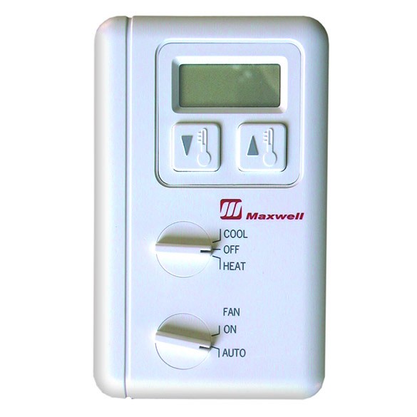
Dumb Thermostat
This is the most absolutely basic type of thermostat. You select a setpoint temperature, and the thermostat will do its best to keep it within the range.
Not-So-Dumb Thermostat
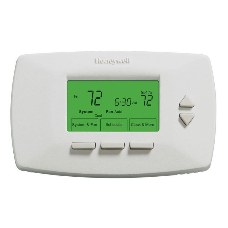
In this category, you will find thermostats that are slightly more expensive, but they deliver significantly more functionality. They are based on the same principals as the dumb thermostat, but they provide you with a much more granular way to specify the temperature.
For example, if you follow a similar schedule every week in terms of what time do you wake up and what time you come back from work, you can program your Not-So-Dumb Thermostat to warm up the house right before you need it and keep it off the rest of the time. This can already result in a great deal of savings for your utility bill.
Smart Thermostat
The Smart Thermostats go a step further to help you save energy at home. Some features that you may find on Smart Thermostats are:
- Ability to program the temperature with a great deal of granularity.
- Presence detection to keep the temperature in check only when somebody is at home.
- Voice control using devices like Google Home or Amazon Alexa.
- Control the settings with your smartphone when you are not home or when you are home, but you are too lazy to walk to the thermostat.
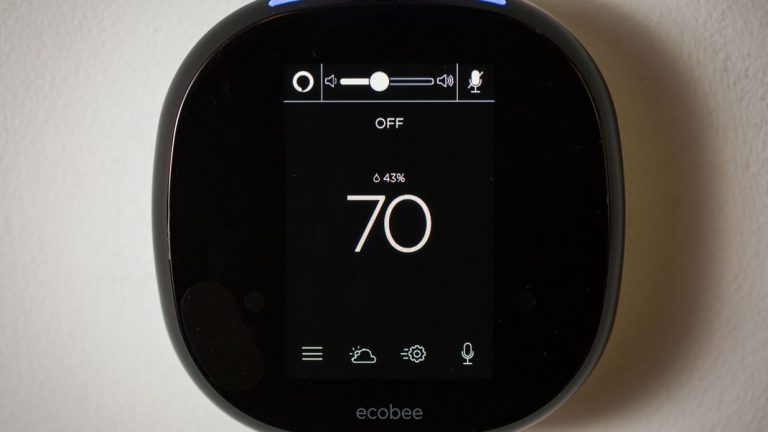
What we are trying to build on this post is the foundations of a Smart Thermostat.
Thermostat Wiring Diagram for Low-Voltage
Here is the last bit of theory before we get down to business building the DIY Arduino Thermostat.
The table below gives you an idea of the color and function of the terminals, according to the industry standards. The tricky part here is that the industry standards aren't always the standard:
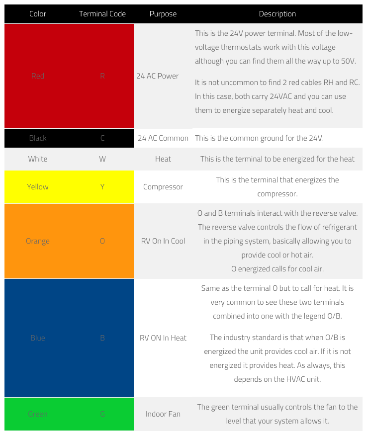

I want to do my best to give you an understanding of what you will find when you open your thermostat, so I will do two things. First, I will give two of the most common examples that you can find. Second, I will provide you with the steps that I followed to find out how mine works. I hope that is helpful.
Thermostat Wiring Diagram: Example 1
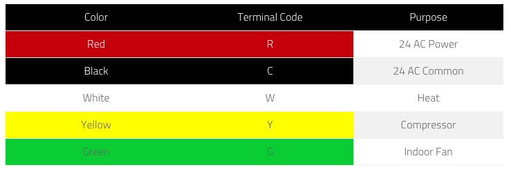 HEAT: In most cases, connecting R to W will turn ON the heat. Sometimes, you also need to connect R to G. But, that depends on your system.
- AC: In most cases, connecting R to Y will turn ON the AC. Sometimes, you also need to connect R to G. But, that also depends on your system.
I say "sometimes," because this depends entirely on the manufacturer, DON'T TAKE ANYTHING FOR GRANTED.
Thermostat Wiring Example 2
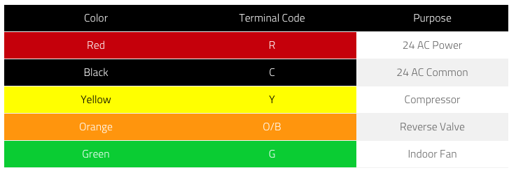
This is a slightly more complicated case.
On this schema, you have to energize Y to start blowing air; then, depending on if O/B is active or not, it will blow hot or cold air. As in the prior case, sometimes, you will have to energize also G.
As I said, this is what I have seen based on my experience replacing thermostats. With that being said, I am not a technician, so there is probably a whole world out there that I don't know about.
To finish this section I want to walk you through the steps that I took to find out how my HVAC thermostat worked. This is what helped me to reverse engineer and replicate the same behavior using relays and an Arduino.
How Does Your Thermostat Work?
1. Open Your Current Thermostat and Check How it Is Wired
If you see five or more thin cables with different colors, chances are that your unit is using a low-voltage thermostat. If this is not your case, it is probably a line-voltage thermostat.
You can also see if the legend on your terminals looks like any of the examples above.
If you remove any of the cables, make sure you take a picture first. If your memory is as good as mine, you won't remember later.
2. Search for Your Thermostat Specs on the Internet
Check what the manufacturer says about the unit. In my case, I needed to connect R to Y to turn on the unit. If O/B is not energized it blows hot air, if it is energized it blows cold air. The terminal G is automatically turned ON when you energize terminal Y.
Trust, but verify.
Even if the specs of your unit are crystal clear, which they are usually not, it is always good to verify that the understanding of the wiring is correct.
3. Verify Your Understanding Using a Multimeter
In order to verify that your understanding is correct, you can use a multimeter. Measure the voltage between the terminal C and the rest of the terminals. Then, set your thermostat on the different modes (AC, HEAT...) and check what terminals are energized on each function.
This will give you a pretty good idea of the terminals that you will have to connect to activate the different modes.
I am sure you know this, but do not ever let the R and C terminals touch; the outcome of this can't be good.
How to Build Your own Smart Arduino Thermostat
While I generally try to write detailed tutorials suitable for everyone, this is most definitely not one of them. I am not an HVAC expert, just a guy with a lot of curiosity that has done some research. So, please, if you decide to do this project, you do so at your own risk. If you don't have at least a basic understanding of electricity and electronics, I would advise against it.
Things That You Should Know Before You Start
- The Arduino Thermostat project is based on the MySensors framework, so you should, first, get familiar with it. I would recommend that you follow the DIY Home Automation Sensors tutorial, because it will help you get up to speed in no time.
- You should have a decent understanding of Arduino and how to program it. If you are not familiar with it, check out Getting Started with Arduino.
- If you haven't played with relays before, check How to control a relay with Arduino. I would add the info here, but — to be honest — the internet is full of tutorials about that.
Shopping List
Here is the list of components that you will need, if you have followed DIY Home Automation Sensors, you should have everything except for the relay board already.
| Units | Description | AlliExpress | Amazon |
| 1 | NRF24L01 | Link | Link |
| 1 | Arduino Nano | Link | Link |
| 1 | Jumper Cables | Link | Link |
| 1 | DHT22 Temperature and Humidity Sensor | Link | Link |
| 1 | 4-Channels – Relay Board |
For this project, I am using the Arduino Nano, mostly, because I don't have size restrictions, but any Arduino will do it though.
What Is Relay?
A relay is an electronically operated switch. Basically, a relay allows us to open and close a circuit driving a high voltage load with a low voltage signal, 5V in this case, like the one that Arduino can provide. This magnificent component provides a small microcontroller with the ability to control devices that require higher voltage, like a bulb.
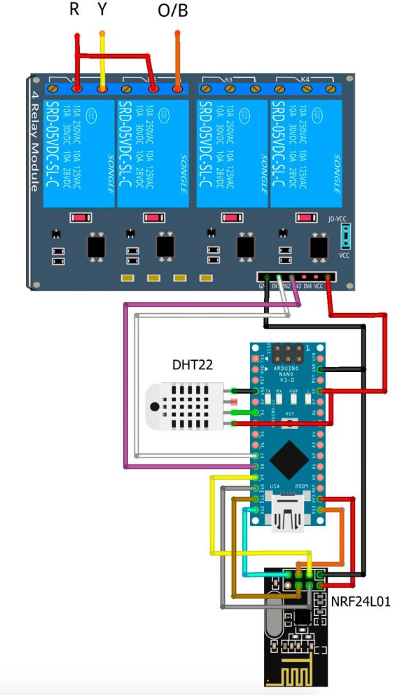
At this point, you might already have an idea of how the relay is going to help us here. The relay will energize the different terminals, connecting R to Y and O/B, which results in our HVAC turning ON the HEAT or the AC.
Arduino Thermostat: Wiring Things Up
If you followed the DIY Home Automation Sensors tutorial, you will only have to connect a few extra wires to get your Arduino Thermostat up and running. The diagram that I am going to show is based on my own Arduino Thermostat. You will have to wire things up based on your own findings, but I can help you do it if you contact me.
Arduino Thermostat Code
Same way as the wiring, the code will be slightly different for your Arduino thermostat. You will need to adapt it to your own needs. I have added comments to the code to try to make it as simple as possible. Pay special attention to the function hvacCommand() and to the definition of the pins for the relays. You should be able to use the rest of the code as it is.
#include <DHT.h>


#define MY_DEBUG
#define MY_RADIO_NRF24
#define MY_NODE_ID 2

//Specify the ID of every sensor. This will help you identifying the MQTT messages.
#define CHILD_ID_TEMP 0 //ID of the temperature sensor
#define CHILD_ID_HUM 1 //ID of the Humidity Sensor
#define CHILD_ID_HVAC_COOL 2 //ID of the sensor that indicates when the AC is ON.
#define CHILD_ID_HVAC_HEAT 3 //ID of the sensor that indicates when HEAT is ON.


//The Pin where the DHT22 sensor is connected.
#define DHT_DATA_PIN 3
//Constant to identify the DHT sensor type. In my case is DHT22
#define DHTTYPE DHT22
//Allows you to define an offset for the temperature. It is useful if the sensor is inside an enclosure for example.
#define SENSOR_TEMP_OFFSET 0
// The relays are controlled by the pin 7 and 8. You can call then in a way that is meaningful to you.
#define RELAY_HEAT 7
#define RELAY_REVERSE_VALVE 8


#include <MySensors.h>

/**************************************************/
/****************** CONSTANTS *********************/
/**************************************************/
//Constant to specify how often will the thermostat evaluate the temperature and take an action. Turn on the AC for example.
static const uint64_t UPDATE_INTERVAL = 10000;
static const uint8_t   = 10;


/**************************************************/
/****************** VARIABLES *********************/
/**************************************************/
//Variables to keep track of the temperature and the humidity.
float   lastTemp;
float   lastHum;
float   temperature = 24.0;
float   humidity;
float   targetTemp = 24.0;
int     statusHVAC = 0;
uint8_t nNoUpdatesTemp;
uint8_t nNoUpdatesHum;

/**************************************************/
/****************** MESSAGES **********************/
/**************************************************/

//Define your mysensor messages to communicate with OpenHab

MyMessage msgHum(CHILD_ID_HUM, V_HUM);
MyMessage msgTemp(CHILD_ID_TEMP, V_TEMP);
MyMessage msgCool(CHILD_ID_HVAC_COOL, V_CUSTOM);
MyMessage msgHeat(CHILD_ID_HVAC_HEAT, V_CUSTOM);

DHT dht(DHT_DATA_PIN, DHTTYPE);


void presentation()
{
  present(CHILD_ID_HUM, S_HUM);
  present(CHILD_ID_TEMP, S_TEMP);
  present(CHILD_ID_HVAC_COOL, S_HVAC);
  present(CHILD_ID_HVAC_HEAT, S_HVAC);
}


void setup()
{

//Before I do anything, I want to make sure that all the relays are opened (nothing is connected)
   //Setup all the Arduino Pins
   pinMode(RELAY_HEAT, OUTPUT);
   pinMode(RELAY_REVERSE_VALVE, OUTPUT);

   digitalWrite(RELAY_HEAT,HIGH);
   digitalWrite(RELAY_REVERSE_VALVE,HIGH);


   delay(2000); //Wait 2 seconds before starting sequence

  dht.begin();

//Load the latest target temperature and status from the eprom, just in case my arduino loses power.
  targetTemp = loadState(0);
  statusHVAC = loadState(1);
}


void loop()
{ //Retrieve teh value of the temperature and the hummidiy from the DHT22
  sendTemperatureHumiditySensor();
  //Take an action opening or closing the relays if needed.
  HVACycle();

  wait(UPDATE_INTERVAL);
}


/**************************************************/
/**************** AUX. FUNCTIONS ******************/
/**************************************************/

//This is the main function, it turn ON or OFF AC or HEAT when the current temperature falls out of range.

void HVACycle()
{

  if(statusHVAC == 0)
    {
    hvacCommand(0,1);
    hvacCommand(0,2);
    printStatus();
    }
  if(statusHVAC == 1)
    {
      if(temperature > targetTemp)
        {
          if(abs(temperature - targetTemp) >= 1)
            {
            hvacCommand(0,1);
            printStatus();
            }
          else
            printStatus();
        }
       else
        {
          if(abs(temperature - targetTemp) >= 1)
            {
            hvacCommand(1,1);
            printStatus();
            }
          else
            printStatus();
        }
    }
  if(statusHVAC == 2)
    {
      if(temperature > targetTemp)
        {
          if(abs(temperature - targetTemp) >= 1)
            {
            hvacCommand(1,2);
            printStatus();
            }
          else
            printStatus();
        }
       else
        {
          if(abs(temperature - targetTemp) >= 1)
            {
            hvacCommand(0,2);
            printStatus();
            }
          else
            printStatus();
        }
      }
}


void printStatus()
{
            Serial.print("\nTemperature: ");
            Serial.print(temperature);
            Serial.print("\nTarget: ");
            Serial.print(targetTemp);
            Serial.print("\nStatus: ");
            Serial.print(abs(temperature - targetTemp));
            Serial.print("\nMode: ");
            Serial.print(statusHVAC);
}

/************ hvacCommand ****************/
/* command: 0 -> ON 1 -> OFF
 *  hvacStatus: 1-> HEAT 2-> AC
 */
/*****************************************/

//This function is very important. It basically describes how to turn ON the AC or the HEAT opening or closing the relays.
//Review it carefully and adapt it to your needs.
void hvacCommand(int command,int hvacStatus)
{
  if(command == 0)
    {
        if(digitalRead(RELAY_REVERSE_VALVE) != HIGH)
          digitalWrite(RELAY_REVERSE_VALVE, HIGH);
        if(digitalRead(RELAY_HEAT) != HIGH)
          digitalWrite(RELAY_HEAT, HIGH);
        send(msgHeat.set(0));
        send(msgCool.set(0));
        }
  else if(command == 1)
      {
      if(hvacStatus==1)
        {
        //When I close the relay between terminals R and Y my unit turns ON the HEAT
        if(digitalRead(RELAY_HEAT) != LOW)
          digitalWrite(RELAY_HEAT, LOW);
        send(msgHeat.set(1));
        }
      if(hvacStatus==2)
        {
        //When I close the relays between terminals R and Y and R and Reverse Valve (O/B) my unit turn ON the AC. Please adapt it to your own needs.
        if(digitalRead(RELAY_REVERSE_VALVE) != LOW)
          digitalWrite(RELAY_REVERSE_VALVE, LOW);
        if(digitalRead(RELAY_HEAT) != LOW)
          digitalWrite(RELAY_HEAT, LOW);
        send(msgCool.set(1));
        }
    }
}

       /* send(msgHeat.set(1)) and send(msgCool.set(1)) are only for accountability purposes.
        *  I want to send a message to my Home Automation Controller when the unit turns ON a function.
        *  It helps me keeping track of the usage.
        */


/* This functions reads the temperature from the DHT22 and send it to the gateway.
 *  You can probabbly use it as it is.
 */

void sendTemperatureHumiditySensor()
  {
  temperature = dht.readTemperature();
  humidity = dht.readHumidity();

  if (isnan(temperature))
    {
    Serial.println("Failed reading temperature from DHT!");
    } else if (temperature != lastTemp || nNoUpdatesTemp == FORCE_UPDATE_N_READS)
      {
      lastTemp = temperature;
      nNoUpdatesTemp = 0;
      temperature += SENSOR_TEMP_OFFSET;
      send(msgTemp.set(temperature, 1));

      #ifdef MY_DEBUG
        Serial.print("T: ");
        Serial.println(temperature);
      #endif
    } else
      {
      nNoUpdatesTemp++;
      }

  if (isnan(humidity))
    {
    Serial.println("Failed reading humidity from DHT");
    } else if (humidity != lastHum || nNoUpdatesHum == FORCE_UPDATE_N_READS)
      {
      lastHum = humidity;
      nNoUpdatesHum = 0;
      send(msgHum.set(humidity, 1));

      #ifdef MY_DEBUG
        Serial.print("H: ");
        Serial.println(humidity);
      #endif
      } else
        {
        nNoUpdatesHum++;
        }
  }

/* This function listens to the gateway to receive the commands
 *  It captures the target temperature and the mode of the Arduino thermostat: AC or HEAT.
 */

void receive(const MyMessage &message) {

    Serial.print(("New message: "));
    Serial.println(message.type);
    Serial.println(message.getInt());

   if (message.type == V_HVAC_SETPOINT_COOL)
    {
      Serial.print("Setting Temperature To: ");
      Serial.println(message.getInt());
      targetTemp = message.getFloat();
      saveState(0, targetTemp); //Save the targetTemperature on the EPROM so you can retrieve if the arduino loses power.
    }

    if (message.type == V_HVAC_FLOW_STATE)
    {
      Serial.print(F("Setting Mode To: "));
      Serial.println(message.getInt());
      statusHVAC = message.getInt();
      saveState(1, statusHVAC);
    }

}
Add the Items to the Home Automation Controller
Here, you have the items of items that you will need to add to your items file, in case you are using OpenHab.
Number thermostat_livingroom_temp           "Target Temperature [%.1f]"  {mqtt=">[mosquitto:mygateway1-in/1/1/1/0/44:state:*:${state}]"}
Number thermostat_livingroom_mode           "Mode [%.1f]"                {mqtt=">[mosquitto:mygateway1-in/1/1/1/0/21:command:*:${command}]"}
Number mqtt_livingroom_temperature          "Temperature [%.1f]"         {mqtt="<[mosquitto:mygateway1-out/1/0/1/0/0:state:default]"}
Number mqtt_livingroom_humidity             "Humidity [%.1f]"     {mqtt="<[mosquitto:mygateway1-out/1/1/1/0/1:state:default]"}
Switch thermostat_livingroom_hvacCool       "HVAC LIVINGROOM COOL"       {mqtt="<[mosquitto:mygateway1-out/1/2/1/0/48:state:ON:1],<[mosquitto:mygateway1-out/1/2/1/0/48:state:OFF:0]"}
Switch thermostat_livingroom_hvacHeat       "HVAC LIVINGROOM HEAT"       {mqtt="<[mosquitto:mygateway1-out/1/3/1/0/48:state:ON:1],<[mosquitto:mygateway1-out/1/3/1/0/48:state:OFF:0]"}
Please, let me know in the comments if there is something that isn't clear or you would like me to add.
Future Improvements
- Add a motion sensor to turn ON and OFF the unit based on the presence
- Add an AUTO mode
- Include external sensors to capture the temperature of the room at different locations
- Include an OLED screen to monitor the temperature
- Anything else? Tell me about it in the comments!
The Arduino thermostat has lots of room for improvement, here are a few things that I recommend:
BK Hobby has great content related to temperature sensors using NodeMCU; if you aren't subscribed to the channel, you are really missing out! I am going to leave you a video about his temperature sensors, in case you want to check it out.
Conclusion
As I said before, this wasn't a step-by-step tutorial but, rather, a walk through. I did a lot of research when I started my Arduino Thermostat Project, and I thought it could be useful for some people trying to do the same.
I hope you learned something today and got an inspiration for your next project.
If you like or hate this post please, tell me about it by email or in the comments. Also, if you have questions, of course, please let me know!
Published at DZone with permission of David Cabanero, DZone MVB. See the original article here.
Opinions expressed by DZone contributors are their own.

Comments