

Make Your Own PIR Motion Sensor
Motion sensors are high-tech security devices you see in the movies, right? Of course not. Learn to make your own motion tracking device.
Join the DZone community and get the full member experience.
Join For Freein this tutorial, we will show you how to build wi-fi pir motion sensor connected to easyiot cloud. we will use a esp8266, a pir module, and the arduino ide.
introduction
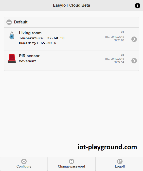

materials
- esp8266 wi-fi module.
- pir sensor.
- 3.3v power supply (battery or regulator).
easyiot cloud configuration
register to the easyiot cloud service. if you do not receive a registration email, check your spam folder. if it's not there, contact us and we will activate your account.
then go to configure->modules->add module. set digital input (di) as the module type and name it pir sensor.
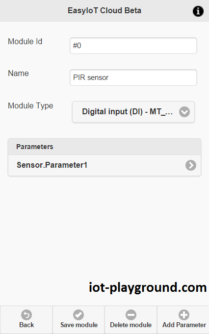
next, click on sensor.parameter1. set "description" to pir and check ui notifications to enable real time notification in the web interface.
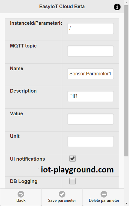
then press the save button. after saving, you will see instanceid/parameterid. make a note of it — you will need it later in program.

go back to module configuration and add two more parameters (add parameter button).
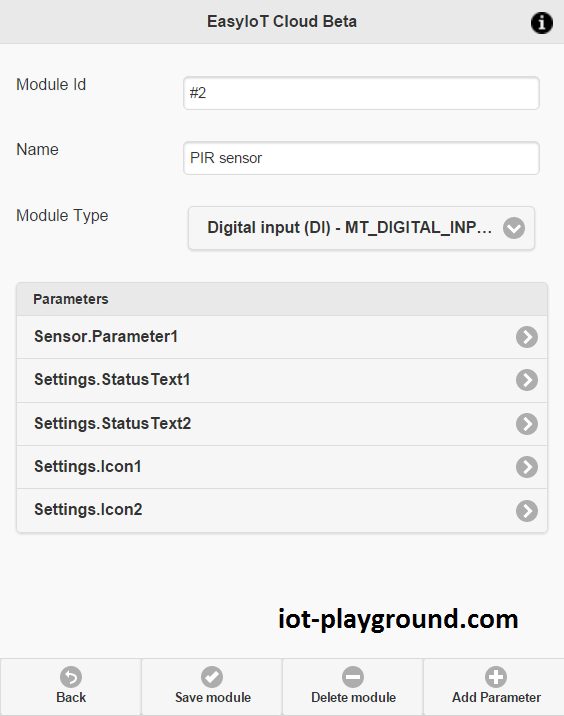
the two parameters are to set text in the module. name the first parameter settings.statustext1 and the second one settings.statustext2. set the value for the first as "motion" and for the second as "ok".
next, we will set a picture for the module. we add two more parameters and name them settings.icon1 and settings.icon2. for the first parameter, set the value to "siren_2.png," and for the second second parameter, set the value as "siren_1.png".
after you add all the parameters, your module configuration should look like this:
program
the program is written in the arduino esp8266 ide. see the arduino esp8266 ide tutorial to learn how to connect your esp8266 module to your computer to upload the program. the program is available at our github . you will also need the eiotcloudrestapi library . in the library, set the access point username and password.
in the program, change eiot_cloud_instance_param_id:
// easyiot cloud definitions - change eiot_cloud_instance_param_id
#define eiot_cloud_instance_param_id "xxxx"
set the instanceid/parameterid in your parameter configuration.
if you change the gpio pin on the esp8266, then also change the gpio pin in the program.
hardware
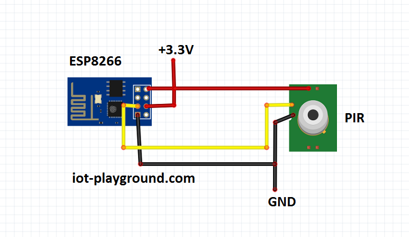
in our case, we use the esp8266 01, but you can use any other esp8266 with the fdti programmer. for your power supply, you can use 2 aa batteries or 3.3v regulator ams1117 (see buying guide).
the pir sensor is powered by 5v, but if we look at the schematic, we will see that it's 3.3v internally. because the esp8266 is 3.3v, we can bypass the pir internal regulator.

the connection after the regulator is available at jp1 pin 3. in our case, we will connect the 3.3v power supply to this point and not to 5v power supply.
you can see it in the following picture:

esp8266 to pir sensor connection
| pir | esp8266 |
| 3.3vcc after internal regulator | 3.3v vcc |
| gnd | gnd |
| out | gpio2 on esp8266 |
and there you have it! enjoy your motion sensor. see more tutorials at http://iot-playground.com/build .
Published at DZone with permission of Igor Jarc. See the original article here.
Opinions expressed by DZone contributors are their own.
Comments